Continue to Site

Welcome to EDAboard.com

Welcome to our site! EDAboard.com is an international Electronics Discussion Forum focused on EDA software, circuits, schematics, books, theory, papers, asic, pld, 8051, DSP, Network, RF, Analog Design, PCB, Service Manuals... and a whole lot more! To participate you need to register. Registration is free. Click here to register now.

Help with antenna simulation

Status
Not open for further replies.

elanus

Junior Member level 1
Joined
Feb 9, 2011
Messages
17
Helped
0
Reputation
0
Reaction score
0
Trophy points
1,281
Activity points
1,433
Hi guys!

I am having a bit of a bummer situation :)

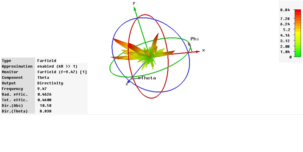
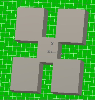
I have simulated a rectangular fractal dielectric antenna, resonating at 9.5 GHz,
and all is nice and fun, until i check the directivity. I have too many main lobes (hope that this is the right translation), and there should be only one.

How can I "get rid" of the others ?

I am using CST Microwave Studio.

Here are some pics of the farfield simulation.

Thanks for your help !
 

It is difficult to say anything without looking at the antenna.
 

Hey !

This is how it looks:
94_1305801891.jpg


εr is 62.
mue is 1.52

i tried playing with height and size, but i cannot seem to get one main lobe. i keep getting tons of them (at least 8 ).
in one simulation, i changed εr to 36, and toyed with size again, and i managed to get one ugly, 30 degrees leaned single lobe, but not close to any readalbe frequency.

please help :p

Thanks!
 

where is your excitation port?
it's not necesary to change εr if you need to get rid lobes. Good directivity is based on optimal coupling between the dimensions of the 5 composants of your antenna. I proposed you to optimize dimensions paramaters using "transient solver-par.sweep"
 

the excitation point is a coaxial feed and it is at about 1/3 of the distance from edge to edge, on the y axis.

and there are not 5 composants. there is only one. i drew it as one object.
 

if you look at the design its like 5 patches making the antenna. Each patch will have its some what main lobe. In patch array feeding network is designed such that the main lobe of all antennas meet and you get single lobe (combined).

Since you do not have feeding network , try making the dimensions of the patches different to one another and see what happens.

This is what could think of.
 

can u suggest me some phd thesis on internet on antenna( microstripe or fractal antennas)
 

Status
Not open for further replies.

Part and Inventory Search

Welcome to EDABoard.com

Sponsor

Back
Top