abhikuvar
Newbie level 6

- Joined
- Mar 5, 2014
- Messages
- 14
- Helped
- 1
- Reputation
- 2
- Reaction score
- 1
- Trophy points
- 3
- Activity points
- 118
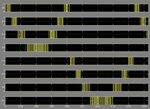
I am trying out a simulink model of 9-level multilevel inverter. I am using SPWM as modulation strategy for it. I am generating SPWM as follows as it is required by MLI

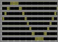
And I am getting the gate signals as follows:

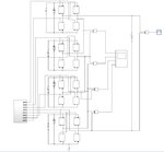
Which I believe are the correct signals for 9-level SPWM Inverter to work properly. But when I apply those signals to the Cascaded H-bridge structure, I am getting just the 4 level weird output rather than 9-level output.
FYI, I am taking reference from 30V,60Hz rms sine wave and having 12V carriers for generating PWM because I am planning to build a prototype with above values.
Please let me know. Your comments are valuable and I appreciate helping me with this. I am attaching simulink model herewith. View attachment spwm_pulsegen.zip

And I am getting the gate signals as follows:

Which I believe are the correct signals for 9-level SPWM Inverter to work properly. But when I apply those signals to the Cascaded H-bridge structure, I am getting just the 4 level weird output rather than 9-level output.
FYI, I am taking reference from 30V,60Hz rms sine wave and having 12V carriers for generating PWM because I am planning to build a prototype with above values.
Please let me know. Your comments are valuable and I appreciate helping me with this. I am attaching simulink model herewith. View attachment spwm_pulsegen.zip


