Continue to Site

Welcome to EDAboard.com

Welcome to our site! EDAboard.com is an international Electronics Discussion Forum focused on EDA software, circuits, schematics, books, theory, papers, asic, pld, 8051, DSP, Network, RF, Analog Design, PCB, Service Manuals... and a whole lot more! To participate you need to register. Registration is free. Click here to register now.

[SOLVED] Help, USB Control Socket keep killing relay

Status
Not open for further replies.

qbone

Member level 3
Joined
Jun 2, 2009
Messages
58
Helped
0
Reputation
0
Reaction score
0
Trophy points
1,286
Location
Lyngby, Denmark
Activity points
1,778
Hello everyone.
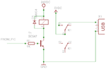
I have recently programmed an adjustable timer in a PIC10F220, and with that I want to control a relay wich turn on and off an USB Control Socket (not sure if thats what they are really called, but this is what I am talking about: USB Control Socket).

I have attached my schematic of how I control the USB port, in the control socket all there is is a 5V relay.

MY problem is that the control sockets relay has died and it it now on constantly, can you see any problems in my schematic?

- - - Updated - - -

So far we are going with the explanation that the Control socket is being overloaded and that is what is killing the relay making it go constant ON.
Since are turning on and off 10 PCs.
 

Attachments

  • schem.png
    schem.png
    4.7 KB · Views: 113
Last edited:

in the control socket all there is is a 5V relay.
Your schematic shows 24V. Is that being used to switch the 5V relay?
What current flows through the transistor?
 

The 24V is controlling the relay which controls the 5V for USB - I didnthave a 5V Relay.
The 5V output goes to the 5V relay in the USB control socket.

I haven't measure the current in the transistor, but it isnt even near the point of failure. The relay that fails is in the USB control socket. But we have now inserted a bigger relay in the USB control socket as we think was the problem. - We'll see.
 

It could just be a poor quality product, with a design flaw, causing the internal 5V relay(s) to fail.
Not much to go on here.
I can't see how your external relay could cause the internal ones to fail.
If the relay is permanently on, it sounds like the contacts have fused together. That's not due to your
external relay circuit.
 
  • Like
Reactions: qbone

    qbone

    Points: 2
    Helpful Answer Positive Rating
You want to control USB port or to control AC mains devices ?

On given circuit is one thing and on photo is another thing.

Describe what you plan to do.

Do you want to control 10 PCs over USB port using PC software (RTC Timer On/Off) ?
 

Hello guys. Thanks for your inputs, but we have solved the issue, as Sky_123 suggested - it was just poor quality. Or maybe we were just overloading, anyway, it helped replacing the relay with a much more powerful one.

I have added a picture that might explain better how it was all connected. We fixed it by letting the relay in the "USB control socket" control a 230VAC relay which can handle alot more current, and that seems to have fixed the whole problem. We are suspecting the peak current from turning all the PCs ON and OFF at the same time. But the important thing is that now it works.
I thank you for your inputs :)
 

Attachments

  • schem.png
    schem.png
    28.5 KB · Views: 118

Status
Not open for further replies.

Similar threads

Part and Inventory Search

Welcome to EDABoard.com

Sponsor

Back
Top