Continue to Site

Welcome to EDAboard.com

Welcome to our site! EDAboard.com is an international Electronics Discussion Forum focused on EDA software, circuits, schematics, books, theory, papers, asic, pld, 8051, DSP, Network, RF, Analog Design, PCB, Service Manuals... and a whole lot more! To participate you need to register. Registration is free. Click here to register now.

HELP: Speed calculation from PWM signal...

Status
Not open for further replies.

dolpre

Junior Member level 2
Joined
Jan 18, 2008
Messages
20
Helped
2
Reputation
4
Reaction score
2
Trophy points
1,283
Activity points
1,424
calculate speed using qep

Hi all,

Plz help me to calculate speed from PWM signal...
i have PWM input into dsp board ( TI TMS320LF2407) from encoder.
may i know how am i going to calculate the speed from this PWM signal?
(this sensor is actually more for position sensor but i have no choice, need to use it)
In the dsp board,i have a CAP input port to capture rising/falling/both edge of the PWM.
Inside the CAP unit, there is a timer. When there is a transition detected, the value of the timer will stored.

Anyone have any idea of it?
Thanks alot...
 

time period for qep signal

The capture input and timer will allow you to know the time between two rising fronts of the signal, for example. This time will be a multiple of the CPU clock period.
All you need to do is invert this value and then multiply it by whatever gain required by your system. You might want to read about fixed point math for this.
For example if one period is 2pi rad, and the timer step is 25ns (40MHz), for a captured value of 100000 you should get about 2500rd/s...
 

fixed point duty cycle calculation

Thanks for your help...
May know what do u mean by invert the captured value of the timer?
For the example u mentioned, can u show the calculation step?

U mentioned that the timer lets me know the time between two rising fronts of the signal. But how can i get to calculate it? I dont understand about this...Because the signal have a frequency of 244Hz, so every 4096us, i will get another rising front of the signal...This is the point i wander....Or i misunderstand regarding this?
*for the timer step, i can choose from 0.025us to 3.2us
 

pwm signal calculation

Hi,

A lot of the answers you seek are heavily dependent on your application. One thing you need to be careful about is the range of speeds you want to measure. This will help you choose the timer step, and you may also have to write extra software if the 16 bits of the timer are not enough at very low speeds.
If you're working with a signal that has a roughly constant frequency (244Hz), your life should be easy and i'd recommend using the 0.025us step.

>May know what do u mean by invert the captured value of the timer?
I meant perform a 1/x calculation

>For the example u mentioned, can u show the calculation step?
you can write it in C and use the "/" operator. Just make sure that the value you choose for "1" is large enough so your result has adequate precision.
Be careful with the range of your variables, since you're using a 16 bit DSP.

example: 244 Hz and a timer at 0.025us gives you 164 in your capture register.
Assuming floating point calculations (that you'll have to convert to fixed point), you want to do:
w = (1/(0.025e-6 * 164)) * 2 * pi = 1532 rd/s
 

pwm speed calculation

In my application, i will need to measure the range of speed from few rpm to ~150rpm. Thus, the speed is quite low in term of rad/s
U mentioned that i may also have to write extra software if the 16 bits of the timer are not enough at very low speeds.
So, do you have any recommendation on that?
What is the extra software u meant for? Can give a sample code/algorithm?


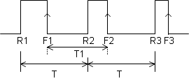
Now, i will like to get the captured value(then convert to time) and then compare with the PWM period, if it is equal the PWM period then mean nothing change to the position, so it is no speed. For example:

96_1206588564.gif


R == rising
F == falling
T == period of PWM(encoder)

If i chose to detect the falling edge of the signal, then the captured value will be from F1 to F1, T1, and it will not be the same as T, period of PWM signal, and this mean that the time is not for one rotation, i.e. 2pi(since the speed i need to measure will not be so fast). Therefore, need to calculate the radian increasing in that period.

d_theta = ((T-T1)/T)*2*pi;

let's say 1cnt ---> 0.025us
163840 cnt ---> 4096us , i.e. cnt for T, period of PWM of encoder

thus, d_theta = ((163840 - cnt)/163480)*2*pi;

speed = d_theta/(cnt*0.025e-6);

*Can you give any comment of my idea on the above calculation?
 

speed calculation pwm

If you need to measure low speeds and you only have 16bits / 0.025us, the slowest you will be able to catch is 610Hz. If you need to go lower than that, I suggest you setup an extra interrupt when the timer reaches 65535, and in that interrupt you increment a counter, which you will reset on the next capture.
Then, the time will be (counter * 65535 * 0.025us) + (capture *0.025us). This will basically give you an extra 16 bits (for an unsigned int counter).
You don't have to do an interrupt, if your main loop is fast enough to check your capture timer frequently.
You also have the option of increasing the capture step.

Now... For your other question. If you are running at low speeds, the best you can do is measure the time between a rising front and a falling one, giving you an indication of speed (scale to pi instead of 2*pi). On the other hand you may want to apply a low pass filter on your estimated speed. The encoder isn't really like a PWM, but more like a variable frequency signal with 50% duty cycle (in steady state).
Now... If what you have is a hi-res encoder, you may want to use the QEP module of the 24xx DSP otherwise your capture module might get overloaded.
Don't forget the "helped me" button !
Regards,
 

    dolpre

    Points: 2
    Helpful Answer Positive Rating
Actually, the encoder i'm using is a high resolution type but it is main for position sensing.
U mentioned that use QEP.
But what i am wander is, how can i implement the it in my case?
Can u explain how to use it? Bcoz i really dont have idea on that as what i am understand is QEP is mainly use for quadrature encoder which have channel A and B

Thanks...
 

Oh, you are right... I'm not sure how the QEP works when you only have one channel. You could experiment with it by possibly connecting your signal to both A and B channels... If you were using the QEP, one thing you could do is calculate the speed at a fixed frequency and use the d_theta given by the QEP.
Speed would be K * dtheta, K being a function of your time step and the unit you're using. This is numerically faster, since it doesn't require an inversion.
It might be better to stick with the capture if this doesn't work. On the other hand you will have to make sure that when you are at high speed your program executes fast enough to not be saturated by all the capture interrupts.
 

Status
Not open for further replies.

Part and Inventory Search

Welcome to EDABoard.com

Sponsor

Back
Top