tehmaas hasan
Junior Member level 1
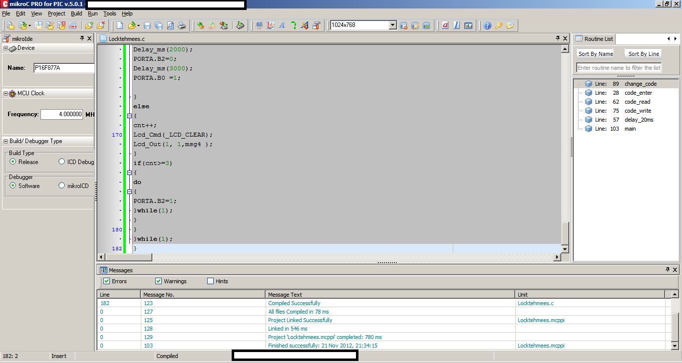
HELP REQUIRED THIS IS THE CODE OF ELECTRONIC LOCK. I CANNOT COMPILE IT ON MIKROC BECAUSE THEre IS MISSING LIBRARY FILE OF KEYPAD SINCE I HAVE NOTE MADE THIS CODE MY SELF I DONT KNOW ITS PROPER LIBRARY FILE.
PLEASE PROVIDE ME ITS LIBRARY FILE(ALL NECESSARY FILES). I WANT TO COMPILE IT AND I REALLY NEED ITS HEX FILE PLEASE HELP ME AS SOON AS POSSIBLE.
PLEASE PROVIDE ME ITS LIBRARY FILE(ALL NECESSARY FILES). I WANT TO COMPILE IT AND I REALLY NEED ITS HEX FILE PLEASE HELP ME AS SOON AS POSSIBLE.
Code:
unsigned short kp;
char code1[10] ,user1[4];
char msg1[20] = "Initializing......",msg2[12] = "Enter Code";
char msg3[15] = "Access Granted",msg4[15] = "Access Denied";
char msg5[15]  = "Enter New Code";
int i=0,j,cnt;

// Keypad module connections
char  keypadPort at PORTD;
// End Keypad module connections

// LCD module connections
sbit LCD_RS at RB2_bit;
sbit LCD_EN at RB3_bit;
sbit LCD_D4 at RB4_bit;
sbit LCD_D5 at RB5_bit;
sbit LCD_D6 at RB6_bit;
sbit LCD_D7 at RB7_bit;

sbit LCD_RS_Direction at TRISB2_bit;
sbit LCD_EN_Direction at TRISB3_bit;
sbit LCD_D4_Direction at TRISB4_bit;
sbit LCD_D5_Direction at TRISB5_bit;
sbit LCD_D6_Direction at TRISB6_bit;
sbit LCD_D7_Direction at TRISB7_bit;
// End LCD module connection

void code_enter()
{
kp = 0;                                // Reset key code variable
// Wait for key to be pressed and released
do
//kp = Keypad_Key_Press();             // Store key code in kp variable
kp = Keypad_Key_Click();             // Store key code in kp variable
while (!kp);
// Prepare value for output, transform key to it's ASCII value
switch (kp)
 {
  case  1: kp = '1'; break; // 1
  case  2: kp = '2'; break; // 2
  case  3: kp = '3'; break; // 3
  case  5: kp = '4'; break; // 4
  case  6: kp = '5'; break; // 5
  case  7: kp = '6'; break; // 6
  case  9: kp = '7'; break; // 7
  case 10: kp = '8'; break; // 8
  case 11: kp = '9'; break; // 9
  case 13: kp = 42; break; // *
  case 14: kp = 48; break; // 0
  case 15: kp = 35; break; // #
 }
code1[i] = kp;
Lcd_Chr(2, i+1, code1[i]);                    // Print key ASCII value on Lcd
i++;
}

void delay_20ms()
{
Delay_ms(20);
}

void code_read()  //Wead data from EEPROM
{
 delay_20ms();
 user1[0] = EEPROM_Read(0x00);          // Read data from address 0
 delay_20ms();
 user1[1] = EEPROM_Read(0x01);          // Read data from address 2
 delay_20ms();
 user1[2] = EEPROM_Read(0x02);          // Read data from address 4
 delay_20ms();
 user1[3] = EEPROM_Read(0x03);          // Read data from address 8
 delay_20ms();
}

void code_write() //Write data from EEPROM
{
 delay_20ms();
 EEPROM_Write(0x00,code1[0]);               // Write some data at address 00
 delay_20ms();
 EEPROM_Write(0x01,code1[1]);               // Write some data at address 02
 delay_20ms();
 EEPROM_Write(0x02,code1[2]);               // Write some data at address 04
 delay_20ms();
 EEPROM_Write(0x03,code1[3]);               // Write some data at address 08

}


void change_code()
{
 Lcd_Cmd(_LCD_CLEAR);                      // Clear display
 Lcd_Out(1, 1, "Enter New Code");

 i=0;
 code_enter();
 code_enter();
 code_enter();
 code_enter();
 code_write();
 code_read();
}

void main()
{
 ADCON1 |= 0x07;      // Configure AN pins as digital
 TRISA = 0x00;          // set direction to be output
 PORTA.B0  =1;
 Keypad_Init();                           // Initialize Keypad
 Lcd_Init();                              // Initialize Lcd
 code_read();
 //If no code is stored then default is 2345
 if(user1[0] == 0xFF && user1[1] == 0xFF && user1[2] == 0xFF && user1[3] == 0xFF )
 {
 EEPROM_Write(0x00,'2');               // Write some data at address 00
 delay_20ms();
 EEPROM_Write(0x01,'3');               // Write some data at address 02
 delay_20ms();
 EEPROM_Write(0x02,'4');               // Write some data at address 04
 delay_20ms();
 EEPROM_Write(0x03,'5');               // Write some data at address 08
 }
 code_read();
 Lcd_Cmd(_LCD_CLEAR);                      // Clear display
 Lcd_Cmd(_LCD_CURSOR_OFF);                 // Cursor off
 Lcd_Out(1, 1,msg1 );
 Delay_ms(500);
 Lcd_Cmd(_LCD_CLEAR);
                       // Clear display
 cnt=0;
 do
 {
 Lcd_Cmd(_LCD_CLEAR);
 Lcd_Out(2, 3, "Press *");
  i = 0;
  code_enter();
  if(code1[0] == 42)
  {
   Lcd_Cmd(_LCD_CLEAR);                      // Clear display
   Lcd_Out(1, 1,msg2);
   //delay_ms(500);
   i = 0;
   code_enter();
   code_enter();
   code_enter();
   code_enter();
   code_enter();
   if(code1[0] == '2' && code1[1] == '3' && code1[2] == '4' && code1[3] == '5' && code1[4] == '5')  //check master code
   {
    code_enter();
    if(code1[5] == 35)
    {
     change_code();
    }
   }
   if(cnt<3 && code1[0] == user1[0] && code1[1] == user1[1] && code1[2] == user1[2] && code1[3] == user1[3] && code1[4] == 35) //compare code with store one
   {
    Lcd_Cmd(_LCD_CLEAR);                      // Clear display
    Lcd_Out(1, 1, msg3);
    PORTA.B0  =0;
    PORTA.B2=1;  //Buzzer
      Delay_ms(2000);
       PORTA.B2=0;
    Delay_ms(3000);
    PORTA.B0  =1;

   }
   else
   {
   cnt++;
    Lcd_Cmd(_LCD_CLEAR);
    Lcd_Out(1, 1,msg4 );
   }
   if(cnt>=3)
   {
   do
   {
    PORTA.B2=1;
    }while(1);
    }
  }
 }while(1);
}
Last edited by a moderator: