Continue to Site

Welcome to EDAboard.com

Welcome to our site! EDAboard.com is an international Electronics Discussion Forum focused on EDA software, circuits, schematics, books, theory, papers, asic, pld, 8051, DSP, Network, RF, Analog Design, PCB, Service Manuals... and a whole lot more! To participate you need to register. Registration is free. Click here to register now.

help : photodiode with TIA

Status
Not open for further replies.
noise.jpg

picture of the noise analysis continued from above
 

Your TIA bandwidth is far too low for the pulse width you are hoping to use. The photodiode has 20pF of capacitance and 50ns rise time with 50 ohm load which is far too slow. You need to be looking at tiny photodiodes with 2pF maximum capacitance, I would think.

If you run a noise analysis you will be able to get the total output noise out of the TIA. Compare that with the signal you expect.

Keith
 

hi,

if my laser pulse width is 20ns ( 5ns rise/fall and 10ns at high ), it means the required TIA output bandwidth is 1/(laser pulse width ) ? which is 1/20ns = 50MHz

or is it 0.34/(laser pulse rise time )? which is 0.34/5ns = 68MHz

i'm pretty confuse with the 2 formulas presented by different papers

and it means my bandwidth output as seen on the analysis SHOULD BE of that much value? 50MHz or 68MHz?

Noted for the noise analysis tips. thank you
 
Last edited:

There is not a lot of difference between those two figures, but for a laser rangefinder it is the precision of the rising edge which is important not the pulse width. For example, if the pulse was 100ns long, it wouldn't help the precision of the edge if you had a low bandwidth based on the overall pulse width.

Keith.

Hi,

Okay thanks for the advice. To be conservative and following the 'rule' that the precision of the rising edge is more important, i shall use the 0.34/tr formula.

May i ask what is the relationship between the rise time of the laser pulse (say 5ns) and the rise time of the photodiode (45ns)? does it add up and so my photo current has a rise time of 50ns?
 

50ns is a long distance in terms of distance travelled by light. You really need to pick a photodiode and amplifier combination which is going to give you more suitable rise/fall times unless you are happy with a precision of several metres. Your minimum range will be quite long as well - it is quite likely that the laser firing will saturate the receiver and the recovery time will be quite long if it is very slow. You can improve that by feeding the received signal through a length of optical fibre to delay it.

Keith.
 

hi,

is that to say, if my laser pulse width is of 20ns, the rise time of my photodiode has to be 20ns or lesser to detect it?

then the min. bandwidth required from the TIA would be 0.34/ ( rise time of photodiode current pulse )?
 

It is a bit more complicated than that. If the pulse is long but the rise time is very fast, you will still detect it with a slow amplifier. e.g if the pulse was 1us with 1ps rise time, to give an extreme example. Why you are losing is the precision of the rising edge, which is critical for laser rangefinders.

The photodiode rise time is usually given into a fixed load resistance (such as 50 ohms). A TIA looks like a resistance but that varies with frequency and the value of the resistance depends on the design, e.g. the opamp used and feedback resistor and compensation capacitor. So, the photodiode could look faster or slower than the datasheet depending on your circuit.

However, in my opinion you should be looking at small photodiodes (I have used 0.2mm diameter ones for maximum speed). The ones you are looking at are far too large and slow. However, you do need to take account of your optics, laser spot size etc.

Keith.
 

hi,

i think i have a better understanding now. So to put that into practice,

i think this photodiode should be better with a rise time of 30ns.

**broken link removed**

does it mean now that in order to detect the photocurrent pulse, i need to have an output bandwidth of at least 1/(30ns) from the TIA?
 

That photodiode has a strange specification. It has only 1pF capacitance but 30ns rise time. I would have expected it to be a lot faster. A good cheap diode is the SFH203 which is 1mm, 5ns rise time and a little over 2pF when reverse biased at 20V.

I would aim for 1/pulse width for the TIA bandwidth and try to keep the edges as fast as possible (you haven't mentioned the distance accuracy you want). The optimum value may be slightly different. I have found there is an optimum where more bandwidth doesn't improve things because it while it increases the signal a little it also increases the noise. You will need to do a bit of optimisation.

Keith.
 

is this the data sheet? SFH203 pdf, SFH203 description, SFH203 datasheets, SFH203 view ::: ALLDATASHEET :::

2pF when Vr is 20V is tested by you? because i don't seem to find it anywhere in the datasheet.

when i do the calculation for Cd, can i take the 11pF instead?

distance accuracy? you mean the distance at which the design laser range finder is suppose to be for? it's from 5m to 4000m if that is what you mean.

Okay, so it's preferably 1/20ns (the laser pulse width) for the TIA which gives 50MHz.

yep, bandwidth > 50MHz will start to induce noise while lesser than that you won't be able to detect the full signal. read it on some paper. Sorry that i kept asking because i have to at least do some mini analyses in about 10 days time to submit a simple report.

Appreciate all the help rendered thus far, shall contribute when i'm wiser and sorry for the duplicated post earlier. cheers
 

This is the device. You need the flat topped version. See the graph on page 4 - bottom right.

By accuracy I mean do you want to know something is 150m +/-1m or 150m +/-10m for example.

You will struggle to detect the 5m without a delay line of some sort.

Keith.
 

Attachments

  • SFH203.pdf
    223.6 KB · Views: 48

hi,

noted for the graph of about 2pF when bias at 20V. It would be the former. +-1m. given the range to reach up to a few kilometres, +- a few metres would be good for me. but i think that concern is secondary for now as i only want to analyze the receiver front end with a few assumptions such as received optical power and stuff.

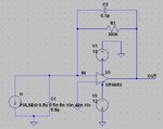
actually for simulating a photodiode, can i really use a pulse current source with the amplitude of the supposed photocurrent?
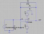
 

hi,


actually for simulating a photodiode, can i really use a pulse current source with the amplitude of the supposed photocurrent?

Yes. Just include the capacitance (as you have done). You could add some leakage resistance, but it is unlikely to be significant compared to photocurrent due to ambient light.

Keith.
 

hi,

i will exclude the leakage resistance for now. just something simple will suffice.

this is the new circuit with calculated compensation capacitor.
circuit.JPG

this is the Vout from the transient analysis
trans.JPG
the output waveform seems pretty distorted (like a sine curve now). the actual photocurrent should be like the simulated pulses and so the ouput will be like that right? what circuit can i get to flatten the peak and amplify it to around 3V to be fed into a TDC?

and this is the response curve:
ac.JPG

The BW is tailored to slightly more than 50MHz for the 1/(laser pulse width). which won't induce excess noise by the op amp and able to detect the full pulse width.

if the results look OKAY to you i shall proceed to analyze the shot noise and johnson noise... at least for some presentation...
 

The output waveform looks like a sine wave because you haven't enough bandwidth. Amplifying and thresholding the signal is another problem. You will need more amplification stages and you will need to AC couple to remove the effect of ambient light. Then a high speed comparator to generate the final signal for the TDC.

Keith.
 

Hi,

You're right. i changed to another OP AMP http://focus.ti.com/lit/ds/symlink/opa653.pdf
and the Vout waveform looks more pulse-like now.
trans.JPGac.JPGcircuit.JPG

why is it that my BW earlier of slighty over 50MHz couldn't even detect the output waveform but this new circuit with about so much larger of 180MHz is able to?

Noted for the second part. talking about AC coupling, i've read some papers where they added in capacitors between voltage sources and the power supply pins of op amps. do i really need them?

This is the tdc i intended to use : **broken link removed**

i think the comparator has already been incorporated in there. alright i shall continue tomorrow it's 1.30am. thanks for your help today! have learnt a great deal! :)
 

why is it that my BW earlier of slighty over 50MHz couldn't even detect the output waveform but this new circuit with about so much larger of 180MHz is able to?
Look sharp at the OPA653 internal circuit. It doesn't work as a TIA, just a 100 ohm or so C/V converter. The output signal is respectively low.
 

Hi,

You mean the output I'm getting is low? They said the transimpedance gain is vout/Iin but I don't get the value of Rf. Partly due to offset but the rest?
 

Look sharp at the OPA653 internal circuit. It doesn't work as a TIA, just a 100 ohm or so C/V converter. The output signal is respectively low.

I understand why is it low. it's cuz the op amp has a FIXED gain. this is good in my opinion as i can give a large resistor for Rf to reduce the johnson noise appearing across it.
 

Status
Not open for further replies.

Similar threads

Part and Inventory Search

Welcome to EDABoard.com

Sponsor

Back
Top