RafidD
Newbie level 4
Hello All,
This is my first post on this website. I am an undergraduate EE student entering my 5th and final year and I have an antenna fabrication question....
I want to fabricate a reconfigurable microstrip patch antenna which will employ PIN Diode switches to change the geometric shape of the patch to acquire different frequencies, hence reconfigurable.
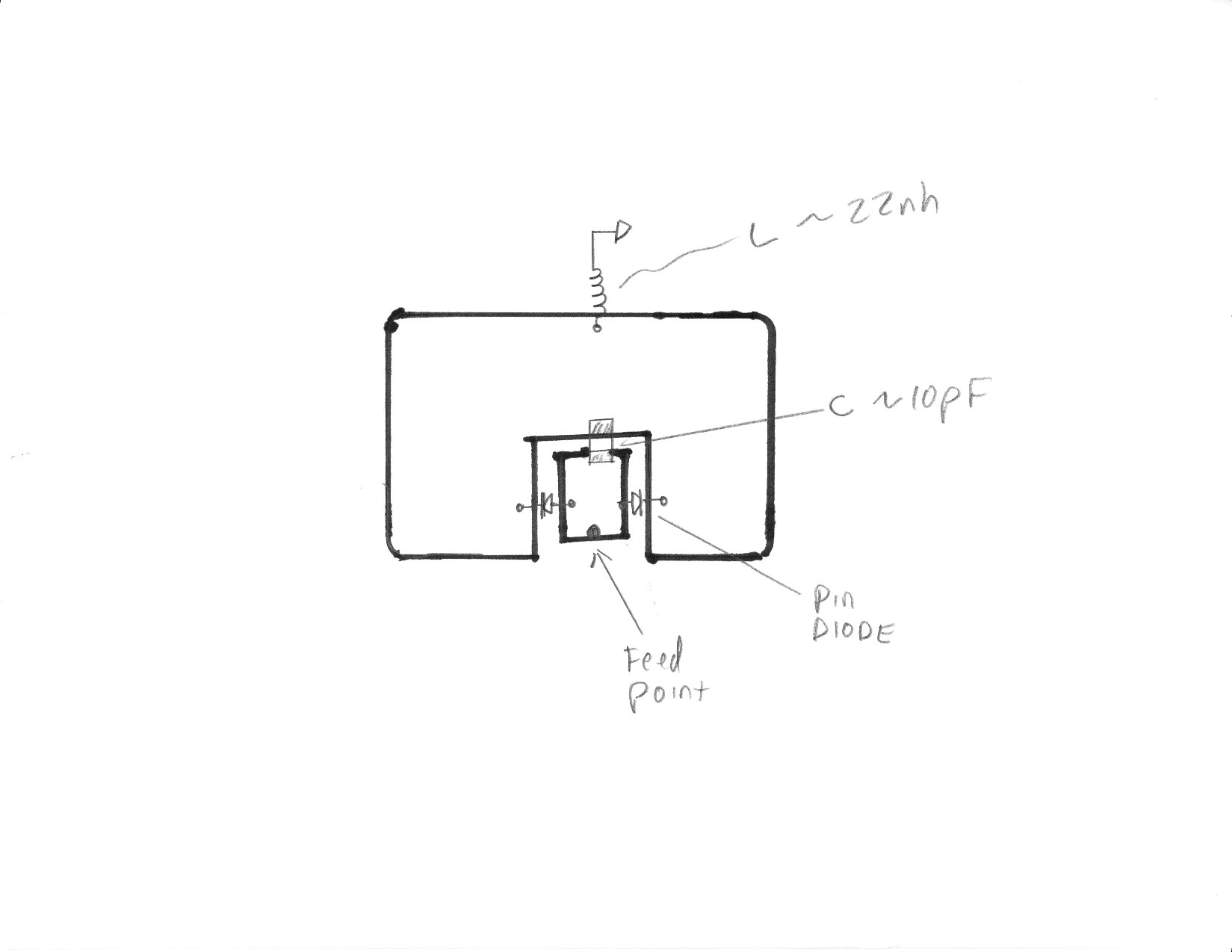
My question is how to utilize the switch? I know I will need the pin diode itself, inductors to be used as RF Chokes (prevent RF signal going into the DC bias lines), capacitors to block DC voltage from entering the antenna or RF signal, and the DC Bias lines themselves to feed the diode power to switch from the Closed (ON) state and Open (OFF) state. But how do I specifically configure this circuit? Series or parallel combination? The size of all parts will be 02-04's (1mmx0.5mm) and the space between the altering patches will be 2mmx2mm.
-Thanks a bunch everyone
This is my first post on this website. I am an undergraduate EE student entering my 5th and final year and I have an antenna fabrication question....
I want to fabricate a reconfigurable microstrip patch antenna which will employ PIN Diode switches to change the geometric shape of the patch to acquire different frequencies, hence reconfigurable.
My question is how to utilize the switch? I know I will need the pin diode itself, inductors to be used as RF Chokes (prevent RF signal going into the DC bias lines), capacitors to block DC voltage from entering the antenna or RF signal, and the DC Bias lines themselves to feed the diode power to switch from the Closed (ON) state and Open (OFF) state. But how do I specifically configure this circuit? Series or parallel combination? The size of all parts will be 02-04's (1mmx0.5mm) and the space between the altering patches will be 2mmx2mm.
-Thanks a bunch everyone