Welcome to our site! EDAboard.com is an international Electronics Discussion Forum focused on EDA software, circuits, schematics, books, theory, papers, asic, pld, 8051, DSP, Network, RF, Analog Design, PCB, Service Manuals... and a whole lot more! To participate you need to register. Registration is free. Click here to register now.
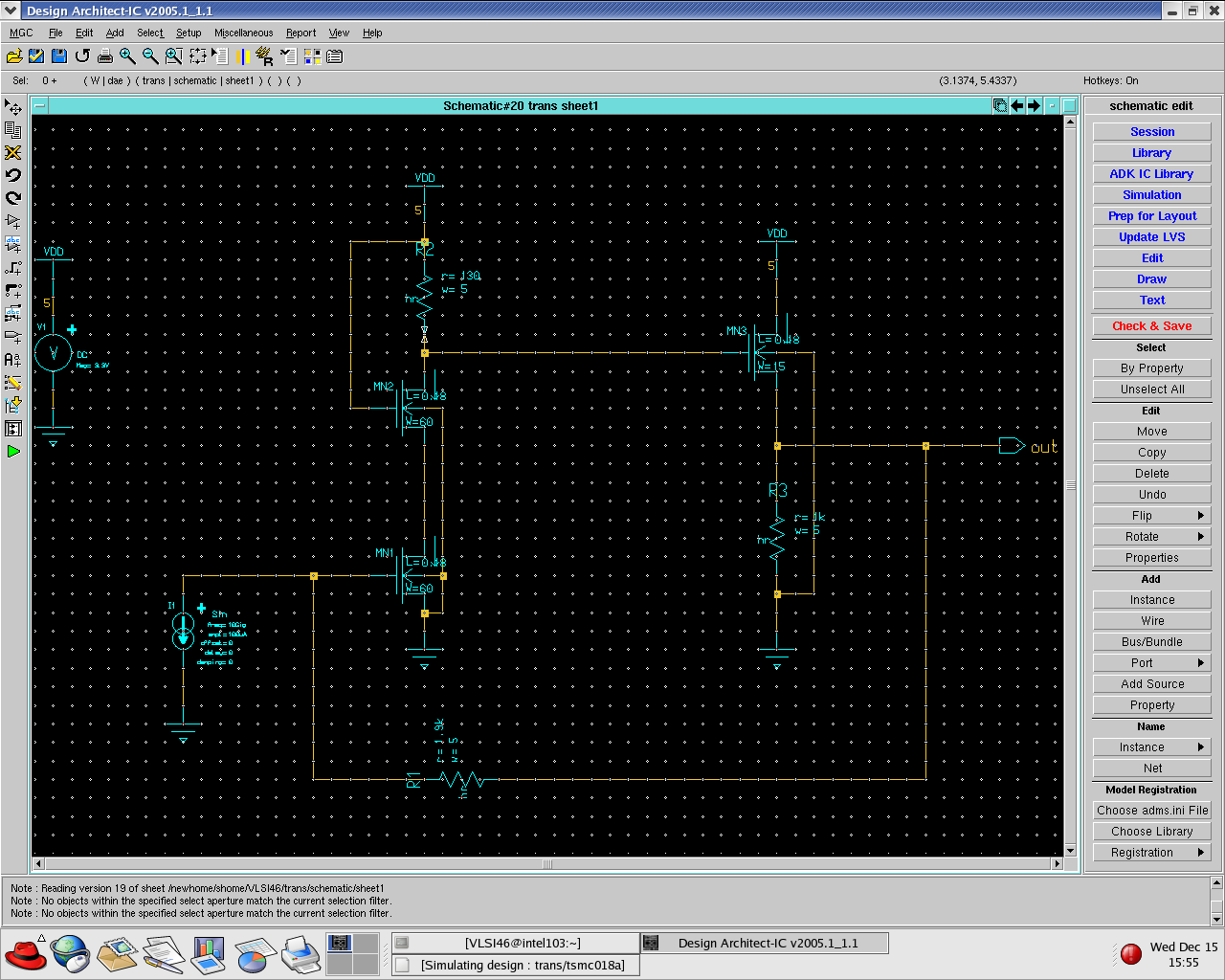
Can someone guide me how to bias my MN2 to saturation mode ?
which component value i need to change ?
Which component will affect the operation mode of MN2 ?
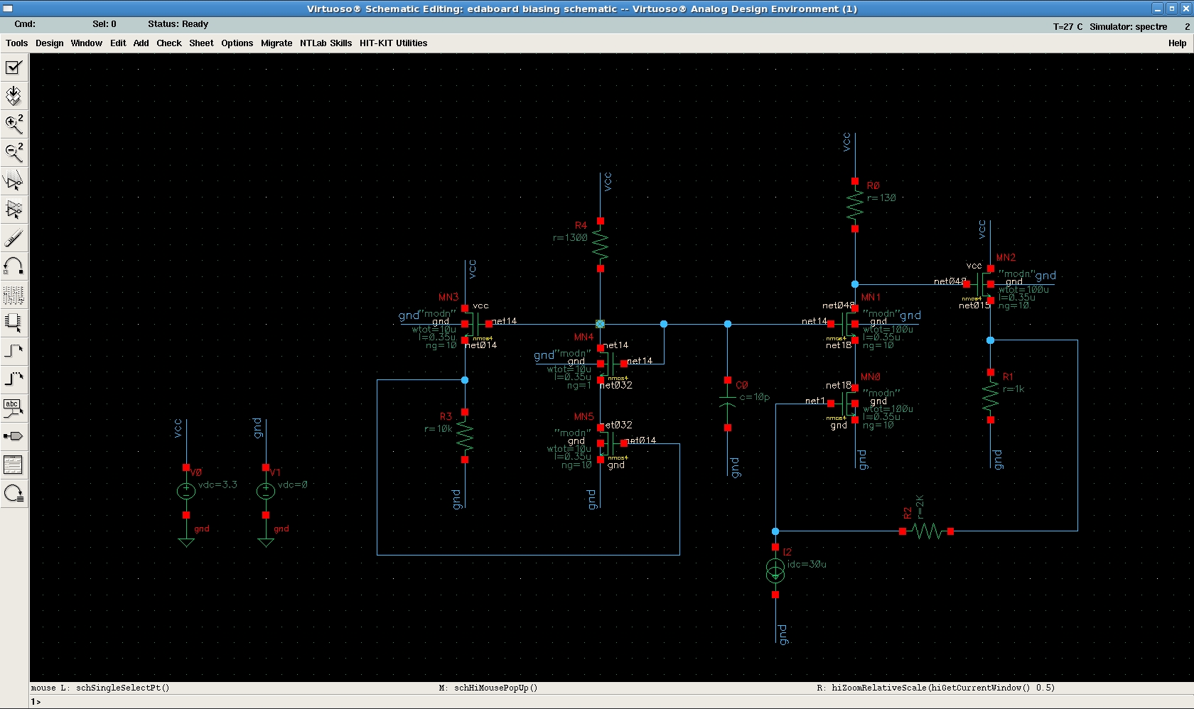
I think, this schematic would work in any technology - i used 0.35 um just for example.
You should choose width (and length) of transistors and value for resistors from noise, gain, current consumption requirements and so on. The general principle of this circuit is in using auxiliary amplifier which is replica of main circuit. Transistors of auxiliary amplifier would have almost the same operation points as those in main. From power management point you can reduce width of transistors in bias circuit (and accordingly, increase value of resistors) as, for example 1:10, so current in auxiliary amplifier would be 10 times lower than in main.
This site uses cookies to help personalise content, tailor your experience and to keep you logged in if you register.
By continuing to use this site, you are consenting to our use of cookies.