Continue to Site

Welcome to EDAboard.com

Welcome to our site! EDAboard.com is an international Electronics Discussion Forum focused on EDA software, circuits, schematics, books, theory, papers, asic, pld, 8051, DSP, Network, RF, Analog Design, PCB, Service Manuals... and a whole lot more! To participate you need to register. Registration is free. Click here to register now.

Help newbie identify chip

Status
Not open for further replies.

Eyeopr8r

Newbie level 5
Newbie level 5
Joined
Dec 10, 2014
Messages
8
Helped
0
Reputation
0
Reaction score
0
Trophy points
1
Visit site
Activity points
62
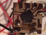
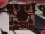
Hi, image.jpgimage.jpgimage.jpgimage.jpgimage.jpgimage.jpg new to forum and not an electronics genius. I need to identify and replace this chip if possible. It's from a family heirloom plastic winky-blinky bow tie my mother bought for me some 25-30 years ago. Ive worn it everyday at work from thanksgiving day until Christmas for about 30 years. This chip makes 10 LEDs on the surface of the bow tie blink randomly. I've managed over these many years to keep it working with various Rube-Goldberg-type repairs, but now either I don't know which wires to solder where on the chip, or the chip is shot. Someone please show pity and help. Ive scoured the internet for hours to replace the actual bow tie itself but they just are no longer made or a available. Thanks
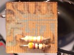
 

After 25+ years it is almost impossible to find exact replacements for any IC, yours is probably made in limited numbers and doesn't even have a manufacturers name on it. Your chances are VERY slim!

From the shadow in the pictures you might be lucky, one of the copper tracks looks to be corroded almost through so it could be the cause of failure. You could try a tiny spot of conductive (silver loaded) paint over it to see if it restores operation. You can buy it at many car parts stores for repairing damaged rear screen heater wires. Only use the smallest amount needed to cover the thin track and leave it at least 24 hours before applying power.

Your best bet though is to make a new one with a modern microcontroller. The total parts cost would be ~$3 US plus a few hours of your time. I would suggest something like a PIC10F200 or similar would be suitable.

Brian.
 

I'm touched by your story and really want to help...
My warm advice - don't try to reverse engineer the old circuit - design a new one yourself instead!

Making 10 LEDs blink on your neck isn't rocket science.
 

Brian,
thanks so much for even taking time to reply to this post. I myself wondered whether the chip might be bad, and could possibly be repaired. My first problem though, is that over the many years of trying rube-goldberg fixes, all the wires are off the chip and I don't know which wire to solder to which connection. I do know which wire is the power, which is ground, and which of the five other wires goes to which pair of LED's, but I don't know where they should attach to the chip (except for the power lead-I know where that goes). Anyway you can tell me where to connect the LED wires and the ground wire?? One of the LED wires supplies power to ALL of the LED'S, so for now I just have all the other LED wires twisted together and soldered to the battery negative terminal plate--which gives me all LED's lit all the time--but I really want to restore the sequential blinking of the LED"s. I know this is a lot of time and effort for such an unimportant item, but it really has become part of our family Christmas tradition within a very large family, and I just am willing to spend the time and try to fix it.
I'm also willing to build a new circuit, but
1. I have no idea how to go about it, or what parts to order,
2. I don't know where to order such parts from.
2. could it be made to a specific size to fit the "slot" for it inside the tie,
3. and if I made a new one, I still don't know which wire goes where.

I really appreciate the advice you have already given. Thanks for any additional help you can give me!!

Ralph


After 25+ years it is almost impossible to find exact replacements for any IC, yours is probably made in limited numbers and doesn't even have a manufacturers name on it. Your chances are VERY slim!

From the shadow in the pictures you might be lucky, one of the copper tracks looks to be corroded almost through so it could be the cause of failure. You could try a tiny spot of conductive (silver loaded) paint over it to see if it restores operation. You can buy it at many car parts stores for repairing damaged rear screen heater wires. Only use the smallest amount needed to cover the thin track and leave it at least 24 hours before applying power.

Your best bet though is to make a new one with a modern microcontroller. The total parts cost would be ~$3 US plus a few hours of your time. I would suggest something like a PIC10F200 or similar would be suitable.

Brian.
 

Gee. I would if I knew how, but I don't know how. Willing to learn how so tell me how to learn. I'm an eye surgeon for crapsake, so just gimme the source to learn how to make one--I don't need an entire electronics education, just the basics of how to build a new one.
 

If someone shows you an electronic schematic circuit - do you think you'll understand how to build the actual circuit from it?
 

OK, I'll go easy on you..... :grin:

That kind of chip is called a 'COB' (Chip On Board) and the whole unit is a small standard construction circuit board witht the working silicon chip glued directly to the board. The wires connecting the chip to the board are spot welded to the silicon at one end and the copper layer of the board at the other. The whole thing is then covered with a blob of black epoxy resin to protect it. There is no way to reverse engineer it without spending a fortune on solvents to remove the epoxy then slicing layers of the silicon while scanning it with a microscope. It isn't a standard 'off the shelf' device and the chances that the manufacturer still exists are remote. Normal ICs have a part number on their plastic body but as that device never had one, it almost certainly bears no identification at all. There is no safe way to work out which pads connect to which function, wrong connection would destroy it anyway.

So realistically, you have to build a new one from scratch. With your expertise in delicate work it should be quite easy and modern microcontrollers are very simple to use. All you need is a very basic, low performance, inexpensive microcontroller. It has everything you need built in to it so functionally it should be a drop in replacement for your old board. The only caveat is that these things are supplied 'blank' and you have to tell them what to do. It involves writing a simple program and a gadget to transfer the program into the chip. I appreciate that is work you probably don't want to do but on a positive note, you can make the LEDS flash in any order you want or randomly. It is all down to how the programming tells them to turn on and off.

I'm not volunteering for this, I'm up to my eyes in other work at the moment but myself and all the other contributors will be very happy to guide you through the process.

Brian.
 

Doubtful. But willing to learn how to read schematic. Gimme simple source.
Thanks
 

Or else tell me where to go to buy one already made
Or to pay someone to make it.
Thanks
 

There may be an alternative although slightly more expensive option that doesn't involve any programming but I need some information before I can help:

1. what country are you in?
2. how big are the LEDs? (can you post a picture of the bow-tie showing them?)
3. how is it powered, type of battery and is it internal to the bow-tie or connected along wires?
4. are all the LEDs the same color and if so, what color are they?
5. can you get to both pins of the LEDs to rewire them if necessary?

Brian.
 

image.jpgimage.jpgimage.jpg
There may be an alternative although slightly more expensive option that doesn't involve any programming but I need some information before I can help:

1. what country are you in?
2. how big are the LEDs? (can you post a picture of the bow-tie showing them?)
3. how is it powered, type of battery and is it internal to the bow-tie or connected along wires?
4. are all the LEDs the same color and if so, what color are they?
5. can you get to both pins of the LEDs to rewire them if necessary?

Brian.

- - - Updated - - -

1. USA
2. See pictures
3. Two 1.5 volt AAA BATTERIES. Everything is internal. See pictures
4. 5 Different colors. See pictures
5. Yes.

See pictures on accompanying post
 

Sorry, I missed the pictures inthe last post. I'm forced to use a mobile phone for internet access at the moment so I disabled images to speed up the downloads.

Those look like 3mm LEDs which are readily available. The other option I mentioned is to replace all the LEDs with ones that have built-in flashers or even color changers. This would allow you to wire them directly back to the battery (through a switch) and dispense withthe COB completely. You would simply wire them all across each other and to the battery.

The flashing ones are single color with a built in timer IC, they only have two wires, all the timing and control is inside them. The color changing ones have three LEDs inside each body, one red, one green and one blue, they either flash one of the colors in sequence or gradually fade one to another. The drawback is they 'officially' work from a 5V supply although I would be fairly confident they would still work at 3V at somewhat reduced brightness. As you don't need much brightness you might get away with it. If there is space inside the tie for a third battery so you can give them 4.5V it would certainly work.

Look on Ebay for "flashing LED" and you will find several suppliers who sell them in bags of 100 for around $5. I use don't wear a bow-tie but I bought bags of 100 and made my own color changing Christmas light show with them! Been working for several years.

Brian.
 

Two series alkaline battery cells are 3V only when brand new. They quickly drop to 2.4V when white, blue and bright green LEDs will not light up. The "3V" continues to drop to only 2.0V but 74HCxxx logic ICs still work like in my "3V Ultra-Bright LED Chaser" project (red LEDs). Which reminds me, two of them need its battery cells replaced because they look dim and chase slowly.
 

Thanks guys!! That seems like a good idea to try. They are glued into the bow tie from inside:-D, so I will see if I can get them out and replace with blinking ones. I will post back the results. also I wouldn't mind if you could give me a source to learn about "programming" micro-controllers. Thanks again for your help!!!

Sorry, I missed the pictures inthe last post. I'm forced to use a mobile phone for internet access at the moment so I disabled images to speed up the downloads.

Those look like 3mm LEDs which are readily available. The other option I mentioned is to replace all the LEDs with ones that have built-in flashers or even color changers. This would allow you to wire them directly back to the battery (through a switch) and dispense withthe COB completely. You would simply wire them all across each other and to the battery.

The flashing ones are single color with a built in timer IC, they only have two wires, all the timing and control is inside them. The color changing ones have three LEDs inside each body, one red, one green and one blue, they either flash one of the colors in sequence or gradually fade one to another. The drawback is they 'officially' work from a 5V supply although I would be fairly confident they would still work at 3V at somewhat reduced brightness. As you don't need much brightness you might get away with it. If there is space inside the tie for a third battery so you can give them 4.5V it would certainly work.

Look on Ebay for "flashing LED" and you will find several suppliers who sell them in bags of 100 for around $5. I use don't wear a bow-tie but I bought bags of 100 and made my own color changing Christmas light show with them! Been working for several years.

Brian.
 

Good luck. Audioguru is quite right about some LEDs needing more than 3V to light up which is why I suggested using three cells if possible. Try them and see if they work with the existing battery arangement. If you find them too dim you can try adding another cell in series if there is space or there are methods for boosting the voltage but they lead you back to needing some electronic construction experience.

If you stick to standard red, yellow and green LEDs there shouldn't be a problem, bear in mind that the ones needing higher voltages hadn't been invented when the tie was made so it must use 'old tech' standard ones at the moment.

Brian.
 

Status
Not open for further replies.

Part and Inventory Search

Welcome to EDABoard.com

Sponsor

Back
Top