Welcome to our site! EDAboard.com is an international Electronics Discussion Forum focused on EDA software, circuits, schematics, books, theory, papers, asic, pld, 8051, DSP, Network, RF, Analog Design, PCB, Service Manuals... and a whole lot more! To participate you need to register. Registration is free. Click here to register now.
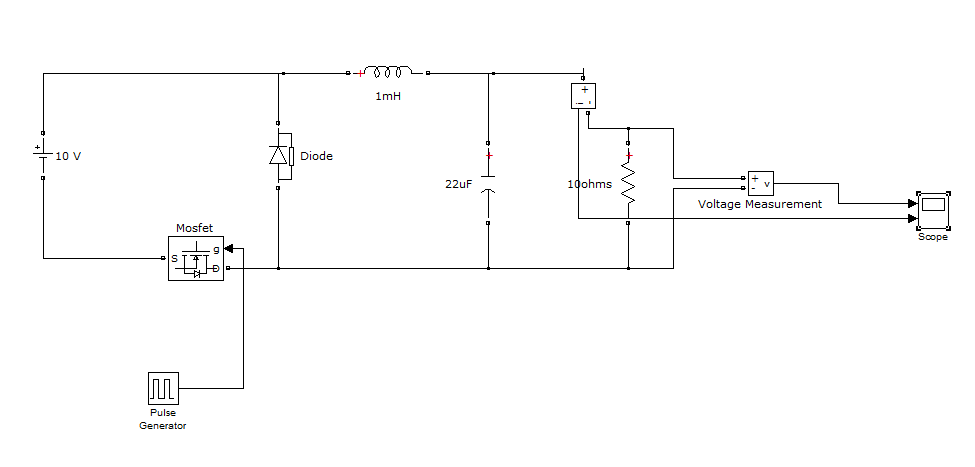
i have attached the circuit diagram.My doubt is whether the loacation of mosfet as low side drive will affect the switching on of diode in the buck converter circuit.
The circuit works as a buck converter but has serious disadavantages:
- no common ground between in- and output
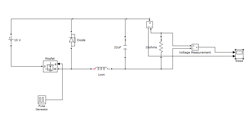
- high frequent AC voltage between in- and output (can be avoided by shifting the inductor to the negative branch)
Thanks a lot FVM.I shifted the inductor.Successfully implemented the buck converter as well as a feedback network that allows the duty cycle to be auto adjusted in order to maintain constant output even if supply is varied(increased or decreased).
This site uses cookies to help personalise content, tailor your experience and to keep you logged in if you register.
By continuing to use this site, you are consenting to our use of cookies.