Continue to Site

Welcome to EDAboard.com

Welcome to our site! EDAboard.com is an international Electronics Discussion Forum focused on EDA software, circuits, schematics, books, theory, papers, asic, pld, 8051, DSP, Network, RF, Analog Design, PCB, Service Manuals... and a whole lot more! To participate you need to register. Registration is free. Click here to register now.

Help Needed for my circuit

Status
Not open for further replies.

rahulpsharma

Junior Member level 2
Joined
Apr 4, 2012
Messages
20
Helped
0
Reputation
0
Reaction score
0
Trophy points
1,281
Activity points
1,481
Hello I've uploaded a circuit and I request some help on this circuit...

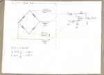
The sensor part: The Sensor part requires +5V DC between Input + & Input - Terminals... So I fed it with a SMPS... +ve of SMPS goes to Input + and Ground of SMPS goes to Input -....

Under no load conditions voltage between Output + & Output - leads, reads as 0.220 mV... As I keep loading the sensor, the voltage between Output + & Output - leads keeps increasing linearly till approx 6 mV...

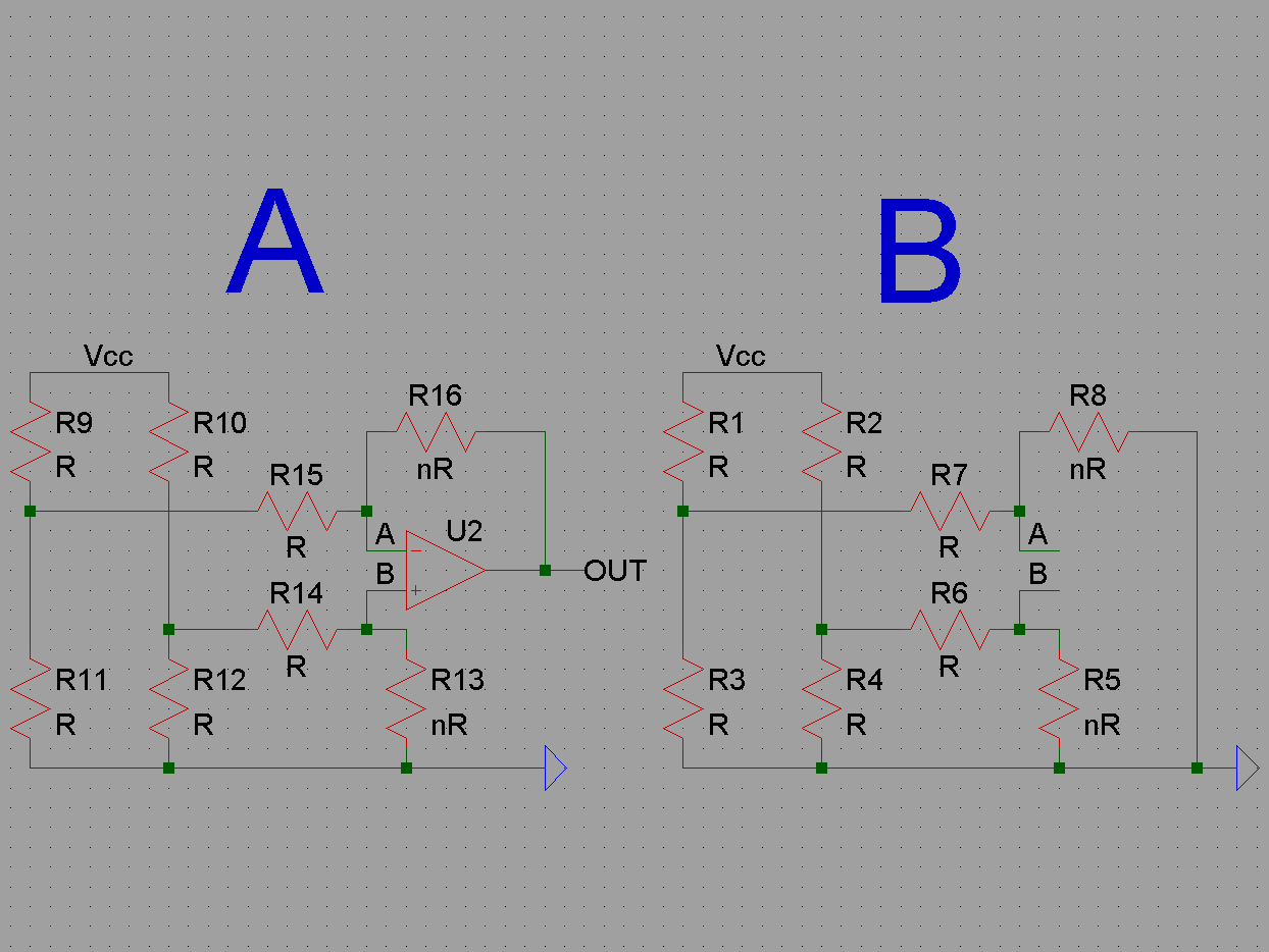
Now I wanted to convert this Output + & Output - to a single ended Output Vo, which can be measured with respect to one single ground, and then fed to another amplifier circuit, which I want to further digitize and do something...!!

So, I tied Output + to Positive Input and Output - to the Negative Input of of Differential Amplifier (Picture Attached), hoping to get a Vo which will be 0.220mV w.r.t to the Ground (Input -)... But my differential amplifier gives an output of 4.75V... I am lost..!!

I would request help my circuit...

Thanks and regards
 

Attachments

  • PTDC0083.JPG
    PTDC0083.JPG
    403.7 KB · Views: 148

" One of the biggest problems with the part in today’s environment is that the OP07 requires dual supplies. A new family of amplifiers from Analog Devices addresses this problem while still giving a close replica of the original specifications. The OP777 single, OP727 dual, and OP747 quad operational amplifiers allow supplies from ±15 V down to ±1.35 V with split rails, and from +30 V down to +2.7 V with single rail operation. "

See figure 3 for a precise bridge design using OP777. **broken link removed**
 
Thanks for the replies... I think that WAS indeed the problem... I had powered up OP07 with +5 VDC and Ground...!!

I would also like to know if I should be worried about the choice of Resistors in Differential Amplifier given the fact that the resistance between Output + & Output - is 1 KOhms...

Currently, I've chosen all resistances of Differential Amp to be 100K Ohms... I was expecting to get exactly what my Fluke is reading between Output + & Output - (i.e., 0.220mV) when read alone without a circuit, however after connecting Out+ & Out- to Diff Amp ckt the output is quite different from that...!!
 

Currently, I've chosen all resistances of Differential Amp to be 100K Ohms... I was expecting to get exactly what my Fluke is reading between Output + & Output - (i.e., 0.220mV) when read alone without a circuit, however after connecting Out+ & Out- to Diff Amp ckt the output is quite different from that...!!

Hi!
It is because your op amp is not in linear mode. See post #2,#4. Close the Output + & Output and receive 0v on output your op amp.
 

I would also like to know if I should be worried about the choice of Resistors in Differential Amplifier given the fact that the resistance between Output + & Output - is 1 KOhms...

The differential amp loads the sensor with an asymmetrical input impedance and causes an error. For high performance you'll want to use a true differential amplifier instead of this "poor man's" diffamp.
 
  • Like
Reactions: tpetar

    tpetar

    Points: 2
    Helpful Answer Positive Rating
The differential amp loads the sensor with an asymmetrical input impedance and causes an error. For high performance you'll want to use a true differential amplifier instead of this "poor man's" diffamp.

Thanks once again...

Is a true differential Amplifier also known as Instrumentation Amplifier...??
 

I've had good experience with the INA series of instrumentation amplifiers from BurrBrown, now Texas Instruments.

You may want to check the website to see any single supply devices.
 
The differential amp loads the sensor with an asymmetrical input impedance and causes an error.
Can you explain more?
5075113600_1369731418.png

If the bridge is balanced and the operational amplifier is in linear mode voltage V OUT is equal to 0. If we ignore the difference between the input currents and the bias voltage of the operational amplifier, the circuit A may be replaced by an equivalent scheme B. Here we see that each of the bridge arms are equally loaded. If the amplifier can not provide the output voltage and enters saturation currents that R15 and R14 are different, and the bridge will be loaded unevenly.
 
Yes, the bridge is loaded symmetrically as long as the bridge is balanced. But even a symmetrical load may significantly reduce the performance of a sensor, e.g. invalidate calibration data shipped with the device. Some bridge sensors like piezoresistive pressure sensors have a temperature dependent source impedance, a load impedance causes additional gain drift in this case. Thus I would prefer a high input impedance instrumentation amplifier. But the single OP circuit can be still good with low and medium peformance sensors as long as it doesn't add significant measurement error.
 
Status
Not open for further replies.

Similar threads

Part and Inventory Search

Welcome to EDABoard.com

Sponsor

Back
Top