btv_murthy
Full Member level 3

Dear Sir,
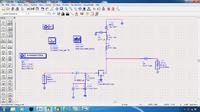
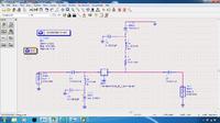
I designed low noise amplifier at 1.3GHz using linear transistor model Avago ATF 54143 , and obtained Gain, Noise Figure and Stability. Now I want to check the linearity of the LNA using IIP3, OIP3, and P1 dB compression point. I have to use nonlinear device model ATF 54143 to measure the IIP3, OIP3, P1dB compression point. What is my doubt is I have connected the nonlinear device model to same circuit and biasing, whatever the circuit and biasing used for the linear device model. I am getting the entirely different results for both linear and nonlinear device model for same circuit and biasing. What is my question is do I need to use the nonlinear device model for measuring IIP3,OIP3, P1dB , Gain and NF? or do I need to use only for linear device model for measuring Gain , Noise Figure and stability, and do I need to use nonlinear device model for measuring only IIP3, OIP3, P1dB or do I need to use the nonlinear device model for measuring both IIP3 , OIP3,P1dB, Gain and Noise Figure and Stability. Can you anybody help me to sort out.
I designed low noise amplifier at 1.3GHz using linear transistor model Avago ATF 54143 , and obtained Gain, Noise Figure and Stability. Now I want to check the linearity of the LNA using IIP3, OIP3, and P1 dB compression point. I have to use nonlinear device model ATF 54143 to measure the IIP3, OIP3, P1dB compression point. What is my doubt is I have connected the nonlinear device model to same circuit and biasing, whatever the circuit and biasing used for the linear device model. I am getting the entirely different results for both linear and nonlinear device model for same circuit and biasing. What is my question is do I need to use the nonlinear device model for measuring IIP3,OIP3, P1dB , Gain and NF? or do I need to use only for linear device model for measuring Gain , Noise Figure and stability, and do I need to use nonlinear device model for measuring only IIP3, OIP3, P1dB or do I need to use the nonlinear device model for measuring both IIP3 , OIP3,P1dB, Gain and Noise Figure and Stability. Can you anybody help me to sort out.


