Continue to Site

Welcome to EDAboard.com

Welcome to our site! EDAboard.com is an international Electronics Discussion Forum focused on EDA software, circuits, schematics, books, theory, papers, asic, pld, 8051, DSP, Network, RF, Analog Design, PCB, Service Manuals... and a whole lot more! To participate you need to register. Registration is free. Click here to register now.

Help me with designing duty cycle detector

Status
Not open for further replies.

RollingEEE

Full Member level 3
Joined
Mar 25, 2006
Messages
165
Helped
8
Reputation
16
Reaction score
7
Trophy points
1,298
Location
Bangladesh
Activity points
2,406
A duty cycle detector

Hi,

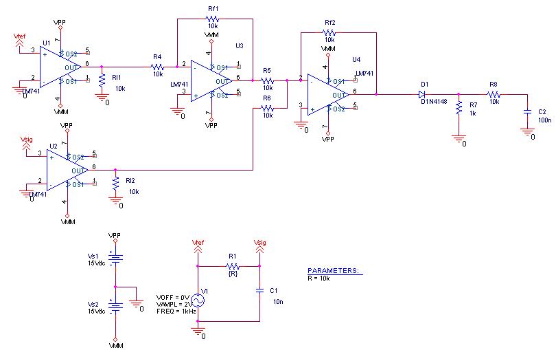
I need a design of an opamp based circuit that takes a PWM signal in, and outputs a voltage, that is proportional to the duty cycle of the inputsignal.

Please help me
 

Re: A duty cycle detector

Integrate the ON part, scale and calibrate
 

Re: A duty cycle detector

nice idea. can you please explain how it works?
 

Re: A duty cycle detector

To provide more information you need to tell more about the application.
Is the frequency fixed?
What will be the max frequency you intend to use?
What type of indication you require. Analog or digital?
 

A duty cycle detector

Typically, what E-design says might be input the signal to the Op-Amp and integrate on a capacitor, with a voltage ratio proportional to the H to L duty cycle, then you can get the result. However, it depends on the input frequency that the Op-Amp can respond and the current it can deliver to the cap that have. Basically, the cap should be large enough to reject the ripples it generate from the switching
 

Re: A duty cycle detector

hi,

I want to make a phase shift detector. I first used 2 level crossing detectors, then used a comparator.

87_1172768959.JPG


The resultant wave was a PWM output the duty cycle was proportional to the phase shift.
75_1172769327.JPG


Using the half wave rectifier yields:
63_1172769450.JPG


Now I need to convert this into something DC. Can any one help me

Added after 9 minutes:

the RC filter gives a regulated DC output but I am not sure if it is linear with pulse width
 

Status
Not open for further replies.

Part and Inventory Search

Welcome to EDABoard.com

Sponsor

Back
Top