Continue to Site

Welcome to EDAboard.com

Welcome to our site! EDAboard.com is an international Electronics Discussion Forum focused on EDA software, circuits, schematics, books, theory, papers, asic, pld, 8051, DSP, Network, RF, Analog Design, PCB, Service Manuals... and a whole lot more! To participate you need to register. Registration is free. Click here to register now.

Help me with Assembly Language for PIC18F4523

Status
Not open for further replies.
check the doc https://ww1.microchip.com/downloads/en/devicedoc/39755a.pdf page 228 Note 1. It is saying something about PBADEN.

---------- Post added at 13:44 ---------- Previous post was at 13:42 ----------

I am creating hex file with mplab and importing it to isis. i will try with btfsc and reply

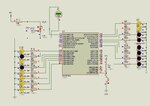
check with this file and also check porta and portb in watch windows of isis. it is not showing the right values.
 

Attachments

  • pic18f4523_4led_4sw.rar
    23.6 KB · Views: 44
Last edited:

check the doc https://ww1.microchip.com/downloads/en/devicedoc/39755a.pdf page 228 Note 1. It is saying something about PBADEN.

---------- Post added at 13:44 ---------- Previous post was at 13:42 ----------

I am creating hex file with mplab and importing it to isis. i will try with btfsc and reply

check with this file

Hi,

Right there is a full datasheet for tht 4523, when I download it only has a shortened version ..?

PBADEN in the config does set the Ports, but I feel its good practice to enter it in the code as not everone realises or uses PBADEN in the Config or is aware of what it defaults to if its not specided in the Users Config code.

Don't forget to use the Delays other wise it does not appear to work properly.
 

can you give me the code for delay 250ms. and where should i add the delay, to the switch debounce?
 

can you give me the code for delay 250ms. and where should i add the delay, to the switch debounce?

Hi,

You can uses either of these , though the 1st one is coded for the 16F and needs the $+ instrcutions changing for the 18F series.
**broken link removed**
http://www.biltronix.com/picloops.html

Once you have tested and found a switch ON , then do a 50ms dela, then test the switch again to ensure it really is on and not just a spike.

If needed, you can also test for when the switch goes off - though generally thats not done, but sometimes a well used switch does stick on...
 

Its not working.
 

Attachments

  • pic18f4523_4led_4sw_2.rar
    23.8 KB · Views: 38

Hi,

Works fine, needed a logic correction with the Switches see the ******'s
The main fault is on the delay subroutine, you had it in a tight loop " dly1 goto dly1 "
 

Attachments

  • 4523.rar
    1,022 bytes · Views: 48

Thank you very much. Now can you help me with displaying some string in lcd (hd44780)
 

Hi,

Those tutorials shown earlier give good examples of how to code the lcd.

If you want a little bit more in depth look at the lcds then have a read at these pdfs.

http://www.epemag.wimborne.co.uk/resources.htm

You will have to remove some of the bank select instructions as virtually all examples are in 16F code, but just copy it over, MPlab will throw out most errors for you to remove or change them.
 
Help me with 4-bit lcd. The problem is with delays. I changed the code for delays from your file
 

Help me with 4-bit lcd. The problem is with delays. I changed the code for delays from your file

Hi,

Must be your lucky day as normally I would not do any further complete module for anyone as they will not learn for themselves.

However that code is a simplified version I did for Vishy, its from the code I use, originally created by Ron K.

Here it is for the 4523.

Note that this is outputting data direct from those 32 calls.

You can store and change the data in 32 user registers, see if you can work that out.

You can also modify it to work by sending out 'strings' of data, very usefull for lots of predefined messages , but not so much if you are wanting to change the display for measurement readings etc.
 

Attachments

  • LCD20.rar
    8.2 KB · Views: 54
Thank once again for taking up so much trouble for me. I'll try to do using user registers. But actually I'll be displaying measurement readings and sending strings of data both.
 

I've done the lcd routine with 32 user registers. Please check it for me.

Can we code using 2 control lines and 4 data lines as it is done in mikroC. mikroC library uses just (RS,E,D7,D6,D5,D4) pins. R/W pin is not used.

There is a
Code:
 loop	goto	loop
what does it do? If I remove it the display refreshes infinitely.

Also check the test file. I have traced the working of lcd routine.
 

Attachments

  • LCD20ur.rar
    8.5 KB · Views: 45
  • lcd working.txt
    3.1 KB · Views: 49
Last edited:

Hi,

Yes the lcd can operate in 6 bit mode, RW must be tied to 0v on the lcd, your code then needs to be slightly modified so it does not need the handshake, just pauses instead.

The loop line, the pic justs sits there in a circle doing nothing else.

You have not quiet got the point about using the Registers.
Cannot go though all the lcd code explaining everything in detail.
For both of these points have a good look at all these links and examples, you should find all the answers there.

**broken link removed**
http://www.sxlist.com/techref/io/lcd/pic.htm
http://www.epemag.wimborne.co.uk/resources.htm
 

Can you check this file. The PORTC leds are not lighting up.
 

Attachments

  • adc.rar
    25.3 KB · Views: 41

Check this also. It is a revision. The ADC value never becomes FFFh, (i.e., 8 + 4 leds doesn't light up) why? It is a 12-bit ADC. 0-5V = 4096 Digital value.
 

Attachments

  • adc_rev1.rar
    26.1 KB · Views: 56

Please check this also. I'm having problem adding a 5us Tacq delay (Tacq 2.96us min needed).
 

Attachments

  • adc_rev2.rar
    1.3 KB · Views: 48

Hi,

Just put the voltmeter across the adc input and you will see the problem, remove the diode and resistor and it works fine.

Re the code, suggests you do not enable GIE while you do not have any ISR entires set up ( see that original template file)
You can still use and test individual interrupt flags though, while the full Interrupts system is inactive.

To dispay the values on the lcd you need a ASCII converter routine , good ones at PicList.com
 

Attachments

  • ScreenShot001.jpg
    ScreenShot001.jpg
    77.1 KB · Views: 50
Hi,

Just Call the subroutine as shown, though why not just let it keep looping around until the result is produced ? or are you trying to set up and error trap incase it does not produce a result and leaves you stuck there ??

Code:
			bsf	ADCON0,GO			; start A/D Conversion
wait_adc		btfsc	ADCON0,GO
								; wait for required acquisition time (if required)
			call	delay5us_20MHz		; how to add delay5us_20MHz here???????
			goto 	wait_adc
 

This is the final version. Check this and do the corrections, 'coz it is not displaying FFFh.
 

Attachments

  • adc_rev3.rar
    25.5 KB · Views: 55

Thanks, It finally worked. That Input was designed for 20V measurement. You are right.
 

Attachments

  • adc_rev4.rar
    25 KB · Views: 46

Status
Not open for further replies.

Similar threads

Part and Inventory Search

Welcome to EDABoard.com

Sponsor

Back
Top