Continue to Site

Welcome to EDAboard.com

Welcome to our site! EDAboard.com is an international Electronics Discussion Forum focused on EDA software, circuits, schematics, books, theory, papers, asic, pld, 8051, DSP, Network, RF, Analog Design, PCB, Service Manuals... and a whole lot more! To participate you need to register. Registration is free. Click here to register now.

Help me understand band pass design in PIR sensor

Status
Not open for further replies.

ericyeoh

Member level 2
Joined
Jun 3, 2009
Messages
46
Helped
1
Reputation
2
Reaction score
0
Trophy points
1,286
Location
malaysia
Activity points
1,635
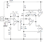
Guys i still dun understand the band pass design in below attrached circuit.

the 1st IC1A and IC1B opamp hv , FL and FH at 1.59hz.

FH = (1/[2(pie) 10mic x 10K]) = 1.59hz
FL = (1/[2(pie) 0.1mic x 1M]) = 1.59hz

how come both cut off frequency at 1.59hz? if this is the case, the bandwidth =0 hz?

Please help me pls, i'm lost
 

Attachments

  • PIR forum.png
    PIR forum.png
    24.5 KB · Views: 110

Re: PIR sensor need help

Your calculations are correct but that doesn't mean you will have zero bandwidth. The cut off frequencies are where the signal has dropped by 3dB. So, the peak response will be around 1.6Hz and it will roll off on either side.

Keith.
 
Last edited:
Status
Not open for further replies.

Part and Inventory Search

Welcome to EDABoard.com

Sponsor

Back
Top