Continue to Site

Welcome to EDAboard.com

Welcome to our site! EDAboard.com is an international Electronics Discussion Forum focused on EDA software, circuits, schematics, books, theory, papers, asic, pld, 8051, DSP, Network, RF, Analog Design, PCB, Service Manuals... and a whole lot more! To participate you need to register. Registration is free. Click here to register now.

[SOLVED] help me to understand the working of the oscillator

Status
Not open for further replies.

diaz080

Member level 4
Joined
Oct 3, 2012
Messages
73
Helped
0
Reputation
0
Reaction score
0
Trophy points
1,286
Activity points
1,714
1.jpg2.jpg
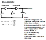
i want to know about the working of this oscillator and how this waveform is obtained..can anyone help me..i know the working of ring oscillator..how this peak value is going to 3/2 vdd ?
 

The two inverters in series are a Schmitt-trigger with positive feedback. The capacitor is charged and discharged by R1 and when its voltage reaches Vcc/2 then V2 switches polarity. The capacitor charges or discharges the peak amount of Vcc/2 so its peak voltage is half Vcc higher than Vcc of half Vcc lower than ground.
R2 allows the voltage of V1 to go higher than Vcc or lower than ground without being clamped by the protection diodes at the input of the first inverter.
 
thanks a lot audioguru.. :-D
 

but one doubt..if i'm simulating this in cadence using real inverters..what will be the deciding factor in sizing the inverter
 

but one doubt..if i'm simulating this in cadence using real inverters..what will be the deciding factor in sizing the inverter
You need good models of the Cmos inverters you are using. An MM74C04 is the same as a CD4069. Their available output current is greater when the supply voltage is higher. If the supply is only 2V to 6V then a 74HC04 inverter IC can be used.
 
hey @audioguru here the deciding factor of frequency is resistor and cap,do the propagation delay has any role in it ? For ring oscillator freq=1/2NTd right..? what about this condition
 

I have never made an oscillator with three Cmos inverters. But I have made many oscillators with only two Cmos inverters.
These oscillators are made with ordinary Cmos which does not produce very high frequencies. Their high frequency performance is much better with a higher power supply voltage. Of course their propogation delay affects their frequency.

For very high frequencies high speed Cmos (74HCxxxx) can be used.
 

Attachments

  • Cmos oscillator.PNG
    Cmos oscillator.PNG
    23.2 KB · Views: 96
here the deciding factor of frequency is resistor and cap,do the propagation delay has any role in it ?
Sure it has. Why are you asking? Check your simulation results.
 
Sure it has. Why are you asking? Check your simulation results.

from the papers i read cmos based rc oscillators are found to be stable with temperature variation and supply variation (around .5 % ) but the propagation delay of the inverter which I used was varying a lot with temperature Since frequency of oscillator is inversely related to propagation delay, how come the frequency is not varying much across different temperature
 

Curiously you didn't mention the intended frequency range.
 
1.jpg i was trying to implement this cmos rc oscillator circuit in cadence.freq of operation 33khz. frequency was not varying much with temperature sweep..but propagation delay found varying sharply..
 

Why do you talk about this odd circuit (too many inverters) on too many threads?

33kHz (I asked what is the frequency on your other thread) is not a high frequency and it is not affected by the propagation delay of ORDINARY Cmos inverters in an ORDINARY Cmos oscillator. But you do not show the supply voltage which might be too low.
 

right now i just want to clarify my doubt regarding the propagation delay variation and frequency stability.sorry for multiple thread posting..need to know about the circuit just mentioned above
 

Status
Not open for further replies.

Part and Inventory Search

Welcome to EDABoard.com

Sponsor

Back
Top