Continue to Site

Welcome to EDAboard.com

Welcome to our site! EDAboard.com is an international Electronics Discussion Forum focused on EDA software, circuits, schematics, books, theory, papers, asic, pld, 8051, DSP, Network, RF, Analog Design, PCB, Service Manuals... and a whole lot more! To participate you need to register. Registration is free. Click here to register now.

Help me measure the impedance of a Zigbee transmitter

Status
Not open for further replies.

Julew

Member level 1
Member level 1
Joined
Apr 7, 2011
Messages
40
Helped
1
Reputation
2
Reaction score
1
Trophy points
1,288
Activity points
1,586
Hello,

I have to measure the impedance of a zigbee transmiter (2.4Hz ISM band). As i read in AN1811 from National Semi (now TI :p) the best way to measure that impendance is with a variable load, variable attenuator and a directional coupler.
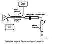
AN1811 Impedance PA measurement.jpg

I havent got too much experience in RF so i dont know how to built the variable load and variable attenuator or where can i buy them. Can i use any variable L/C as variable load? Can i solder them in a perforated pcb with some SMA connector?

I buy componentes in normal distributors like farnell, digikey, amidata, mouser...

Thanks!

Julen
 

Re: PA impendace measure

You can buy variable attenuators with SMA/N/BNC connections on them. They are typically purchased as pieces of test equipment, so generally aren't cheap for one-time use. If this is for a school project, then consider using something that the school already has. I'm not sure about the variable load, unless you mean something like a sliding short.

By using a series variable attenuator, and terminating the load with the sliding short, you can cover a majority of the Smith chart. I'd imagine you'd find the optimum impedance by getting the lowest reflection at the reverse port of the coupler. Is that what the article you found says?

If you have access to a VNA, then you could use that to make your measurements. Just be sure to put enough attenuation between the PA output and the VNA input, so that you don't blow out the delicate recevier circuitry inside the VNA (VERY expensive to repair).
 
  • Like
Reactions: Julew

    Julew

    Points: 2
    Helpful Answer Positive Rating
Re: PA impendace measure

Hello,

We have a spectrum analyzer and an adaptor to measure S11: (R&S FSH6+FSH-Z2). The article says that you can not measure the output impedance with a VNA:

Measuring the input impedance of a receiver or passive antenna
is simple. A calibrated VNA will display the value on its
screen. However, when measuring the output impedance of
a power amplifier or transmitter, this technique cannot be
used because the power being transmitted will completely
disrupt the VNA reading. The technique of conjugate matching
using a variable load must be used.

How can we measure it with our equipment?? Where can i buy the "sliding short"? Thanks!!!

Julen
 

Re: PA impendace measure

I think is a small mistake in the application note from National (perhaps they were too enthusiastic thinking to the 6.5 billions in cash from TI)
The Power Meter should be connected to the forward port of the coupler, and not to the reverse port, because here is about to measure the maximum forward power when the output matching is optimum.
Or you can let the power meter to the reverse port, but have to tune the load for minimum reverse power. In this way if VSWR is high, have to calculate what is the maximum available power.
 
Why don't you use sliding tuner to measure the output impeance ??? If you connect a power meter at one side and when complex conjugate condition is satified, you'll obtain maximum power.
Then you can measure the input impedance of other side by terminate 50 Ohm at first side..
It's straightforward..
**broken link removed**
 
Re: PA impendace measure

Hello,

We have a spectrum analyzer and an adaptor to measure S11: (R&S FSH6+FSH-Z2). The article says that you can not measure the output impedance with a VNA:

How can we measure it with our equipment?? Where can i buy the "sliding short"? Thanks!!!

Julen

I disagree. I've use older HP VNA's to do "Hot S22" measurements on PAs before. You just need to be careful about how to couple and calibrate your setup.

There are much easier ways to measure the impedance, as vfone and BigBoss mentioned. Look into them first. If they are too expensive (which Maury might be), you can go back to these analog techniques, but you'll just have to suffer with low resolution in your answer.
 

    V

    Points: 2
    Helpful Answer Positive Rating
Hello Julew,

I assume your spectrum analyzer with S11 adapter will only measure the modulus of S11.

About conjugate match. A power amplifier is designed to give a certain amount of power into a predefined load (for example 50 Ohms). This does not mean that the output impedance of the amplifier will be (around) 50 Ohms.

A PA design based for maximum gain will operate under conjugate match condition, but a design for better efficiency may show complete other output impedance. When using "tuning for maximum output" this will very likely result in more power, but reduced efficiency and not meaningful result.

So I think you should measure the output impedance with 50 Ohms load. As you don't have means to measure phase, you can use a slotted line to measure output impedance.

You need an attenuator and two signal sources. The attenuator is connected to the slotted line and the output of the amplifier goes to the other input of the slotted line. Source 1 you use to drive the power amplifier. The attenuator is to protect source 2 against excessive reverse power.

Source 2 you connect to the attenuator and is tuned about 100 kHz to 1 MHz away from frequency of source 1. Adjust Source 2 so that about 0.1% of the PA's output power is sent towards the PA. So if your PA gives 100mW, you need to send about 0.1 mW towards the PA.

Now connect the spectrum analyzer to the sliding voltage probe and tune the analyser to the frequency of source 2. Make sure that the peak from the PA itself doesn't saturate the spectrum analyser. Note that you may see side bands that are generated by the PA. If these sideband are above -15 dB (w.r.t. carrier of source 2), reduce power of source 2.

When you move along the slotted line, you may notice the VSWR pattern along the line. From this pattern you can calculate the complex output impedance of the PA. You need reasonable knowledge of cable transmission theory (as you also have to calibrate your setup), and it is time consuming, but this method can give reasonable results, Without the need for a VNA or VSA.

A microstrip line (or ground plane backed CPW) you can use as slotted line. The probe can be just a capacitive pick-up wire that probes the E-field along the microstrip. The CPW has the advantage of having a ground present on the same side as the signal carrying trace.
 

Hello!

I have read that i can measure the output impedance of radio transducer configuring it as input and reducing the output power of VNA to measure the S11 (-30dBm -40dBm). This methord for me is perfect. The problem is that whit my equpment i cant control de output power: -10dBm (it can modify the Z of the transducer). Can i put a atenuator in the output of the generator??

---------- Post added at 10:10 ---------- Previous post was at 10:09 ----------

Where should i install the attenuator??? In point 1 or 2?


Where should i install the attenuator??? In point 1 or 2?

I think that if i buy a 20dB attenuator and i place it in point 1 i´m going to have the VSWR diagram moved 20dB down and if i place it in 2 40dB. Is that correct??

Thanks a lot!!!!
 

Status
Not open for further replies.

Part and Inventory Search

Welcome to EDABoard.com

Sponsor

Back
Top