Continue to Site

Welcome to EDAboard.com

Welcome to our site! EDAboard.com is an international Electronics Discussion Forum focused on EDA software, circuits, schematics, books, theory, papers, asic, pld, 8051, DSP, Network, RF, Analog Design, PCB, Service Manuals... and a whole lot more! To participate you need to register. Registration is free. Click here to register now.

Help me design a 1/2 kW SMPS 2-50V 0-10A

Status
Not open for further replies.

karthick1987

Member level 2
Joined
Jul 4, 2012
Messages
49
Helped
10
Reputation
20
Reaction score
10
Trophy points
1,288
Location
Sydney, Australia
Activity points
1,631
Hi guys,


I am trying to make a Switch mode power supply at the moment, which takes 100-240V AC input and outputs variable DC from 2-50V and 0-10A. I would like some pointers as to what I need to do before putting my thoughts together. I have previously made DC power supplies using a transformer and full wave rectifier. But I find that to be to chunky and quite inefficient. So if you guys have any references to SMPS designs or something you have done yourself, please let me know. I have done a bit of research on some Gate drivers for the output stages (IR2110) and some power FETS (P and N type).

I have also had a confusion as to whether I should use positive or negative switching at the output stage. When it comes to feedback as well I am not sure how to go about it. I also plan on using a micro on board

Please advice

Regards
Karthick
 

Re: 1/2 kW SMPS 2-50V 0-10A

Hi Karthick
Your specifications are ok . you can achieve it with a simple forward converter or perhaps a push pull converter as well . at first you should see datasheet of these integrated circuits :
UC3845 or SG3526N or TL494 . the idea for variable voltage is take feedback with two resistors and a reference voltage and an opto coupler and an op amp ! thus you can achieve 2.5 volts up to each voltage that you want ! however if you want 0-Xv , it is possible too ! but it needs some experiences , at first ! .
About variable current , you should use an op amp too ! an op amp and then a low value resistor and then a variable reference voltage , thus you can achieve your desired current as well from zero up to each value that you want .
and you told that you need some references for design , well there are many references available , but these are better : Switching power supply design by abraham pressman . and switch mode power supply cookbook by marty brown . but there are many other things available such as application notes or free pages on the net !
Let me discipline what i have suggested to you ! at first read datasheets of those integrated circuits that i have suggested . thus we can continue .
Best Wishes
Goldsmith
 
Re: 1/2 kW SMPS 2-50V 0-10A

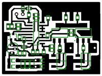
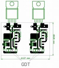
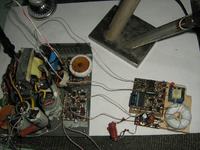
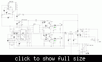
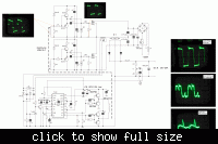
Something have done myself.
Works quite well, but was got excessive in a complicated way.
 
Re: 1/2 kW SMPS 2-50V 0-10A

Hi deepone
Some comments on your presented circuit :
1- why half bridge ? because it needs more components . 2- and why those externally components ? ( transformer driving and those BJTs ?) . 3- why not a simple float driver instead of those components ?
Regards
Goldsmith
 

Re: 1/2 kW SMPS 2-50V 0-10A

Hello there DeepOne,

When you refer that "was got excessive in a complicated way", what you mean by that?

can I ask you a couple of question about the schematic?

Regards.
 

Re: 1/2 kW SMPS 2-50V 0-10A

Hi Deepone,

It seems to me like you need several transformers. I was under the impression that one would suffice

Goldsmith,

Thanks for the info. I am going to go step by step as suggested. I shall read the datasheets and also downloaded both the books. Thanks for that.

One question: I was under the impression that SMPS used one transformer which stepped up the voltage to ~400V AC and then got rectified, chopped (PWM) and finally filtered. Is that a right approach ?

Thanks guys.
 

Re: 1/2 kW SMPS 2-50V 0-10A

DeepOne,

You are driving the MOSFET through transformer? Why you haven't used the turn ratio equal?

I can't understand the part of the 2 capactior of 47nF (at input). Can you explain that?
 

Re: 1/2 kW SMPS 2-50V 0-10A

One question: I was under the impression that SMPS used one transformer which stepped up the voltage to ~400V AC and then got rectified, chopped (PWM) and finally filtered. Is that a right approach ?
Yes , it is right ! but you will have a transformer before 2nd rectifier and filter . ( Ferrite transformer ) . by the way if you couldn't download those books i can send them to you via email ( i can't attach them here because it is kind of infraction . )
Best wishes and good luck
Goldsmith

- - - Updated - - -

You are driving the MOSFET through transformer? Why you haven't used the turn ratio equal?

I can't understand the part of the 2 capactior of 47nF (at input). Can you explain that?
I think he/she have used that capacitor to neutralize the effect of wires ! it is a usual solution to use a capacitor nearby collector or drain for totem pole circuits or main switches to prevent some resonant effects ( unwanted resonant )
 

Re: 1/2 kW SMPS 2-50V 0-10A

It is not to set the ground rail? If he didn't used that, how would be the schematic?
 

Re: 1/2 kW SMPS 2-50V 0-10A

Hi Goldsmith.
- why half bridge ? it needs more components.
basically by reason of easier make powerful transformer
why those externally components ? ( transformer driving and those BJTs ?)
transformer driving for galvanic uncoupling, BJT and not a simple float driver for reliability. And else this is interesting for me - look as all this will work in realities.

Hello AMSA84
"was got excessive in a complicated way", what you mean by that?
I mean surplus amount of transformers and inductors ).
Why you haven't used the turn ratio equal?
To provide spare for making the negative offset on gates. Possible do on other way, but i want to try this way.
I can't understand the part of the 2 capactior of 47nF (at input)
this is half-bridge capacitors, it must be calculated on sufficient power.
 
Last edited:
  • Like
Reactions: FvM

    FvM

    Points: 2
    Helpful Answer Positive Rating
Re: 1/2 kW SMPS 2-50V 0-10A

I still not understand why those capacitor are there. And in that way, how you use the 1:40 and 4:1 transformers on that part. Maybe is the way that the schematic is drawn.
 

Re: 1/2 kW SMPS 2-50V 0-10A

1:40 current sensor, ring in which pass through wire from main transformer as primary windings.
4:1 transformer is main transformer, amount of turns in which depends on used ferrite core, for example 40 primary and 10 secondary turns.
 

Re: 1/2 kW SMPS 2-50V 0-10A

Strictly speaking it's 4:1+1, I think.
 

Re: 1/2 kW SMPS 2-50V 0-10A

Strictly speaking it's 4:1+1, I think.
Yes, sure.
Possible try to refuse from gdt, but i not certain about that will work with such feedback on voltage.
 
Last edited:

Re: 1/2 kW SMPS 2-50V 0-10A

basically by reason of easier make powerful transformer
Hi Deepone !
Agreed !

not a simple float driver for reliability
I'm disagree about this ! float drivers are guaranteed for high voltages ! ( there are easily available ) . however if you need pretty safe process ( for example in a high voltage system ) , an opt coupler would be ok ! but still i'm in this believe that a float driver is good because of linear and predictable behavior ! hardly i use a transformer as driver in my SMPS designs . ( in transmitters it is a safe and good way but here it is unnecessary ! ) . it is my opinion but of course you can be disagree with me .
In addition : a transformer can change matching between your main PWM ( it's dead time ) , and reflected PWM . and it is possible that you see some oscillations in it's out put .
Another thing : you have used four transistors in primary . you could use just two transistors and a capacitor ! ( in series ) and for the secondary just an RCD network !
But i love circuits like yours ! because it benefits from some good configurations ! :-D
Best Regards
Goldsmith
 

Re: 1/2 kW SMPS 2-50V 0-10A

If the frequency of the PWM was about 200kHz, could the size of the transformers used be reduceD? and would it make it more efficient?
 

Re: 1/2 kW SMPS 2-50V 0-10A

Transformer size can be reduced with increased switching frequency, at the same time efficiency will usually drop due to increased switching losses. The effect can be compensated by using faster transistors and better circuits and first of all a lot of design experience. It's not an option for power electronics beginners.
 

Re: 1/2 kW SMPS 2-50V 0-10A

Hi
At first glance I thought it is 2 transistor forward mode convertor due to the output inductor. btw what is the minimum voltage at the input which should be acceptable to this converter mean 110v to xxxx.
 

Re: 1/2 kW SMPS 2-50V 0-10A

Yes, it's a half-bridge forward converter. As any forward converter, it has a limited voltage adjusting range. It can accept 110V input, but with half output voltage only.
 

Status
Not open for further replies.

Similar threads

Part and Inventory Search

Welcome to EDABoard.com

Sponsor

Back
Top