obrien135
Full Member level 5
- Joined
- Nov 10, 2009
- Messages
- 240
- Helped
- 5
- Reputation
- 10
- Reaction score
- 5
- Trophy points
- 1,298
- Location
- Connecticut
- Activity points
- 3,259
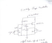
Re: Clapp Oscillator
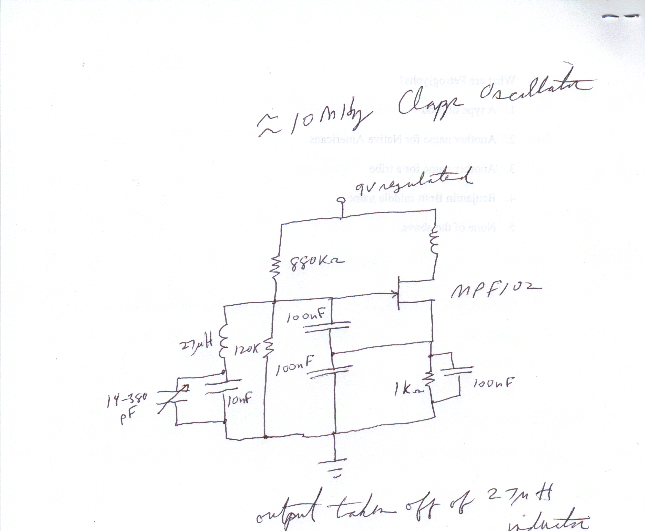
This is the circuit

Added after 8 minutes:
I am having trouble using the edaboard tools to post an image, but the above image is a Clapp oscillator which I built. Can anybody see whats wrong with it? It shows no sign of oscillation.
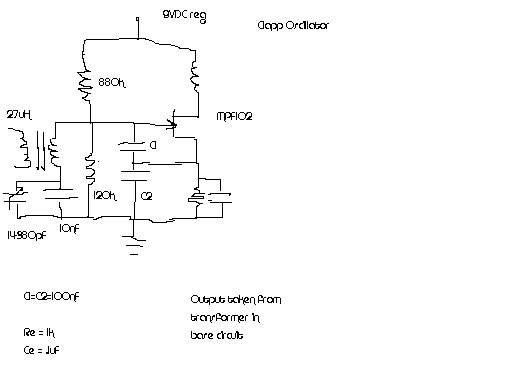
Added after 3 hours 25 minutes:
Here is a better picture of it.
Added after 36 minutes:
Do I need the 120Kohm resister?
This is the circuit
Added after 8 minutes:
I am having trouble using the edaboard tools to post an image, but the above image is a Clapp oscillator which I built. Can anybody see whats wrong with it? It shows no sign of oscillation.
Added after 3 hours 25 minutes:
Here is a better picture of it.
Added after 36 minutes:
Do I need the 120Kohm resister?