Continue to Site

Welcome to EDAboard.com

Welcome to our site! EDAboard.com is an international Electronics Discussion Forum focused on EDA software, circuits, schematics, books, theory, papers, asic, pld, 8051, DSP, Network, RF, Analog Design, PCB, Service Manuals... and a whole lot more! To participate you need to register. Registration is free. Click here to register now.

Help identifying components.

Status
Not open for further replies.

Sci-Guy

Newbie level 6
Joined
Oct 12, 2006
Messages
12
Helped
0
Reputation
0
Reaction score
0
Trophy points
1,281
Activity points
1,379
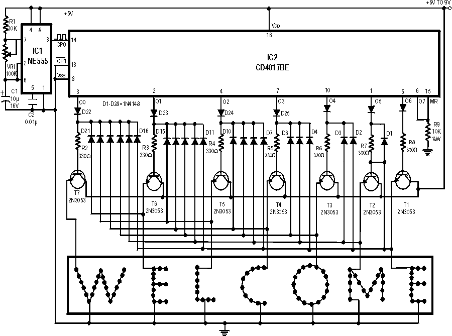
Hey guys & gals. I'm just getting started in electronics (beginner hobbyist). I came across this schematic for a project that I'd like to have a go at building. However, due to my novice status, identifying components on a schematic sometimes gives me grief. I know what most things are on this schematic, with the exception of CP0 & CP1. Is there any chance that somebody here could explain what CP0 & CP1 are? The description that accompanied the schematic doesn't mention either CP0 or CP1, yet they are there on the schematic. Being unable to identify theses components is preventing me from gathering the needed components for the project.
88_1163268991.gif


Thanks in advance.
 

Thanks melc.

I wasn't expecting such a quick reply.
 

Well, I've built the above circuit, only to find that it doesn't do what it should. While it does light up all the LEDs, it doesn't light them progressively. In fact, each time I connect the power supply, a different number of the LEDs light up (sometimes all of them). The potentiometer doesn't appear to have any effect on the circuit. I consulted the appropriate datasheets for the ICs to ensure I had the correct pinout.

As the components for this project have cost me in excess of AU$60.00, I'd like to get it working. After all, I could have lit the LEDs statically at a fraction of the cost. However, as a complete novice to electronics, troubleshooting the circuit is beyond my abilities.

I'd really apreciate any suggestions anybody might have regarding possible causes of my problem.

I should add that, after initially powering the circuit, I found that I had wired one of the transistors wrong. After correcting this, the problem still exists. Could this have caused any damage to components?
 

Sci-Guy said:
I should add that, after initially powering the circuit, I found that I had wired one of the transistors wrong. After correcting this, the problem still exists. Could this have caused any damage to components?
It shouldn't. Anyway, check if you have clock getting out from 555 to 4017. Check if you used proper values of resistors and capacitors, that 0.01µF could be written as .01 on real part, or 10nF.
 

sinip,

Thanks for your reply.

I have checked and double checked all values and they are right.

I'm not sure I know how to check the clock. However, according to my multimeter, pin 3 of the 555 has a constant voltage of 0.02V. Would I be right in assuming that this should change momentarily during each pulse? If so, does this mean the 555 is damaged? I had considered this possibilty due to the fact that I soldered directly to its pins. Unfortunately, I don't have another to replace it until I get to my local supplier tomorrow. In hindsight, I should have used sockets for both ICs.

Is there a better way to check the clock?

I apologise for all the newbie questions but, as stated above, I'm a complete novice.

Edit: Just to add, I connected an LED (with resistor) between pin 8 of the 555 (+Vs) and pin 3 (output) and the LED stays constantly lit up.
 

Sci-Guy said:
sinip,

Thanks for your reply.

I have checked and double checked all values and they are right.

I'm not sure I know how to check the clock. However, according to my multimeter, pin 3 of the 555 has a constant voltage of 0.02V. Would I be right in assuming that this should change momentarily during each pulse? If so, does this mean the 555 is damaged? I had considered this possibilty due to the fact that I soldered directly to its pins. Unfortunately, I don't have another to replace it until I get to my local supplier tomorrow. In hindsight, I should have used sockets for both ICs.

Is there a better way to check the clock?

I apologise for all the newbie questions but, as stated above, I'm a complete novice.
No need to apologise at all. The best way to check the clock would certainly be with an oscilloscope, but if you have frequency counter on your multimeter, or logic probe, it should do as well. Depending on actual frequency that 555 should provide, you may not be able to see any change on voltage range, because it could simply be too fast. And yes, you might got it damaged by soldering, if you overheated it. Anyway, in the meantime you can download datasheet for 555 from www.datasheetarchive.com just type in NE555 and then compare factory application note with your schematic to see if anything looks odd...
 

Try to adjust the potentiometer VR1
My 555 calculator show for VR1 middle point – 50K, 555 frequency about 2.4 Hertz and duty cycle about 54%
This will give measure of 2 - 2.5vdc in VDC multimeter mode

Take care on C1 polarity
Electrolyte capacitor, the sign is the – pin
Tantalum capacitor, the sign is the + pin
 

Can I safely assume that the multimeter setting with the square wave symbol is the frequency counter? If so, I get no change in the value (1) shown on the multimeter.

Added after 10 minutes:

Jepeto,

Thanks for your reply.

While adjusting the potentiometer gives changing voltage readings at its own pins, it has no effect on the output of the 555.

As to C1, I took great care in making sure I had the polarity right (it's an electrolytic).
 

Can you measure the voltages on the different pins and post for reference? Put the pot in mid position before you measure.

TOK ;)
 

I've replaced the potentiometer with a 56K resistor (still not working, of course). The pins of the 555 show the following voltages:

Pin 1 = 0.01V
Pin 2 = 4.18V
Pin 3 = 0.02V
Pin 4 = 5.16V
Pin 5 = 3.74V
Pin 6 = 4.17V
Pin 7 = 5.28V
Pin 8 = 5.59V

Just out of curiosity, I broke the track at one end of R1, and the LEDs began to light progressively (sort of). After a couple hours, the LEDs were fried (I have more), so this is definitely not an option.
 

You can do test to verify if 555 fault
Disconnect 555 pin 3 from IC2 pin 14
Connect IC2 pin 14 to 1K – 10K resistor and the resistor second pin to VDD (IC2 pin 14)
With wire short several times between CP0 IC2 pin 14 to VSS IC2 pin 8
This will clocked the counter, you should see the LED ON changes
 

Connect IC2 pin 14 to 1K – 10K resistor and the resistor second pin to VDD (IC2 pin 14)

So the resistor loops back onto the same pin?
 

Sci-Guy said:
Connect IC2 pin 14 to 1K – 10K resistor and the resistor second pin to VDD (IC2 pin 14)

So the resistor loops back onto the same pin?

Sorry – VDD IC2 pin 16
 

If you're only getting 0.2 volts on pin 3 that suggests to me that maybe the 555 isn't running and producing a clock or maybe you're using an anaolgue meter? Shop around for a multimeter that can also do frequency, there are many in the affordable range that go up to 50 kHz or so.

An early project for you might be a PIC-based frequency counter? I can give you the details of one I adapted from the Weeder one on p1clist.com, it's good up to 40 MHz :D
 

Sci-Guy said:
I've replaced the potentiometer with a 56K resistor (still not working, of course). The pins of the 555 show the following voltages:

Pin 1 = 0.01V
Pin 2 = 4.18V
Pin 3 = 0.02V
Pin 4 = 5.16V
Pin 5 = 3.74V
Pin 6 = 4.17V
Pin 7 = 5.28V
Pin 8 = 5.59V

Just out of curiosity, I broke the track at one end of R1, and the LEDs began to light progressively (sort of). After a couple hours, the LEDs were fried (I have more), so this is definitely not an option.

Since the voltage on pin 6 is above the threshold level of about 3.66V, pin 7 should have been at 0V or around that. If you have connected this pin directly to 5V sometimes, you could have blown it to heavens, since this is a open collector output. I would try another 555, but you need to take care where you put the power this time.

If your LEDs are fried you need to add current limiting resistors in series with them. You haven't posted this part of the schematics.

TOK ;)
 

OK, I'm a little embarrassed to admit this, but.......I discovered that I had inadvertantly used 10Ω resistors for R1 & R9, instead of 10KΩ (my eyes have begun to deteriorate these last couple years). Not knowing what other components may have been damaged by this stupid mistake, I'm going to start from scratch, replacing everything. Unfortunately, other commitments require me to leave this project for a few days.

Thanks for taking the time to assist me with this, guys. Your replies have, at the very least, helped me to understand this circuit (or, more correctly, its components) just a little better than I did before. I'll post back to let you all know whether I get this going or not.
 

Jepeto said:
Try to adjust the potentiometer VR1
My 555 calculator show for VR1 middle point – 50K, 555 frequency about 2.4 Hertz and duty cycle about 54%
This will give measure of 2 - 2.5vdc in VDC multimeter mode

Take care on C1 polarity
Electrolyte capacitor, the sign is the – pin
Tantalum capacitor, the sign is the + pin

mind providing me with a link to the calculator?
 

Jepeto said:
Try to adjust the potentiometer VR1
My 555 calculator show for VR1 middle point – 50K, 555 frequency about 2.4 Hertz and duty cycle about 54%
This will give measure of 2 - 2.5vdc in VDC multimeter mode

Take care on C1 polarity
Electrolyte capacitor, the sign is the – pin
Tantalum capacitor, the sign is the + pin

The online 555 calculators that I tried, using 50K value for R2 (VR1), gives frequency of 1.31Hz and 54% duty cycle. I only tried two of them, but with the same results. Is it possible that they are both wrong?

The text that accompanied the schematic states, "The timer NE555 (IC1) is wired as a 1Hz astable multivibrator which clocks the IC2 for sequencing operations." This seems to verify the results from the online calculators.
 

Results are correct

On line Calculators
**broken link removed**
 

Status
Not open for further replies.

Similar threads

Part and Inventory Search

Welcome to EDABoard.com

Sponsor

Back
Top