Continue to Site

Welcome to EDAboard.com

Welcome to our site! EDAboard.com is an international Electronics Discussion Forum focused on EDA software, circuits, schematics, books, theory, papers, asic, pld, 8051, DSP, Network, RF, Analog Design, PCB, Service Manuals... and a whole lot more! To participate you need to register. Registration is free. Click here to register now.

[SOLVED] [HELP] Hybrid coupler 90 degree hfss disscussions

Status
Not open for further replies.

yiepzz

Newbie level 3
Joined
Dec 21, 2010
Messages
4
Helped
0
Reputation
0
Reaction score
0
Trophy points
1,281
Activity points
1,312
hello..
I want to design a 4x4 butler matrix. As we know, butler matrix is consisted of hybrid, phase shifter, and crossover (CMIIW). So i must design each of them properly to make a butler matrix.

I am designing hybrid coupler 90 degree in ansoft hfss now. I am newbie in ansoft simulation..so i can't read well the results.
Work frequency is ranging from 2.35 GHz to 2.44 GHz. The I get the center frequency is 2,3945 GHz. Using copper for the patch and ground plane in 0.035mm, duroid 5880 for the substrate with 1.6mm.
I put my work in attachment..feel free to take a look :oops:

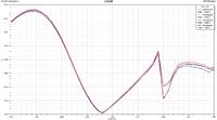
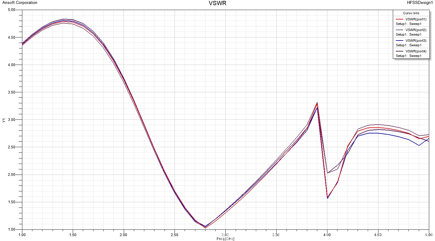
Here is some VSWR results..

How to optimize my design in ansoft? :-?

And the last question.. as we know hybrid can shift the phase of the outputs. Output in port-3 is 90 deg from the port-2. How to analyze that?? How to read the phase-shift in ansoft?

Please correct my design if needed.. I'm just newbie in ansoft simulation

So many thanks to you all... :grin:
 

Attachments

  • Hybrid@2,394 - Copy.zip
    13.3 KB · Views: 159

Hi, yiepzz

I think it's better lay lumped ports in the middle of sheets, but you put them at sides
Assigning lumped port you can shift phase by 180 deg (changing direction of arrow)

Assigning voltage excitation you can set the desired phases and even magnitudes.

Good luck

---------- Post added at 13:47 ---------- Previous post was at 13:31 ----------

Check if every lump port' sheets contact with patch and groundplane.
I think that 3-rd not contacting with groundplane

---------- Post added at 13:51 ---------- Previous post was at 13:47 ----------

Why you did patch and groundplane as solids but not as sheets?
 
  • Like
Reactions: yiepzz

    yiepzz

    Points: 2
    Helpful Answer Positive Rating
Hi, yiepzz

I think it's better lay lumped ports in the middle of sheets, but you put them at sides
Assigning lumped port you can shift phase by 180 deg (changing direction of arrow)

Assigning voltage excitation you can set the desired phases and even magnitudes.

Good luck

---------- Post added at 13:47 ---------- Previous post was at 13:31 ----------

Check if every lump port' sheets contact with patch and groundplane.
I think that 3-rd not contacting with groundplane

---------- Post added at 13:51 ---------- Previous post was at 13:47 ----------

Why you did patch and groundplane as solids but not as sheets?

I think the port-3 is connecting patch and groundplane.. please let me know if i've missed something..

Hm..IMHO, I used solids for groundplane and patch because i want to set the thickness of each them.
I'll try to make a new one with sheets then and add voltage excitation..
 

Structure is symmetrical, but field is not

Better to avoid to specify such more digits after point as you did (for example Wz0 = 4.929877517), 2-3 will be enough

Becose program round's numbers to larger or smaller and then there can be no contact.
 
  • Like
Reactions: yiepzz

    yiepzz

    Points: 2
    Helpful Answer Positive Rating
Structure is symmetrical, but field is not

Better to avoid to specify such more digits after point as you did (for example Wz0 = 4.929877517), 2-3 will be enough

Becose program round's numbers to larger or smaller and then there can be no contact.
Thankyou for your comment bro :)


Anyway.. I've decided build a new hybrid.. in 2.4 GHz. Then the results...
VSWR:
**broken link removed**

S-Parameters :
**broken link removed**

Phase:
**broken link removed**
ang_deg(S(port1,port1)): 170.045899545400690
ang_deg(S(port1,port2)): -146.290644403338040
ang_deg(S(port1,port3)): 123.812787962548170
ang_deg(S(port1,port4)): 10.949562298852058
@2.4 GHz.

I can't get the phase correctly in this hybrid.. would you like to tell me how to get the correct phase?
What is the meaning of S-Parameters? Why are there a "crossover" in my second images?

Feel free to correct and comment my design :)
 

Attachments

  • Hybrid2,4.zip
    9.8 KB · Views: 154
Last edited:

Status
Not open for further replies.

Part and Inventory Search

Welcome to EDABoard.com

Sponsor

Back
Top