nagaraj.m
Newbie level 5
hi all
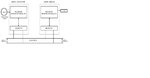
im doing a project on CAN bus using PIC18F458 microcontroller. im using mikroC compiler.i hav attached the block dia below...i got this proj from dogan ibrahim book.i implemented the below block in two bread boards.but i cannot see the temp value on LCD.the program is executed fine in mikroc.....i donno wher the problem is....LCD shows the 'CAN bus" which is programmed in the display node...kindly help me how 2 check whether the data is being transmitted in CAN bus.also if there is any mistake in program pls reply me....thanks in advance

the collector node program is
the display node program is
kindly reply frnds
im doing a project on CAN bus using PIC18F458 microcontroller. im using mikroC compiler.i hav attached the block dia below...i got this proj from dogan ibrahim book.i implemented the below block in two bread boards.but i cannot see the temp value on LCD.the program is executed fine in mikroc.....i donno wher the problem is....LCD shows the 'CAN bus" which is programmed in the display node...kindly help me how 2 check whether the data is being transmitted in CAN bus.also if there is any mistake in program pls reply me....thanks in advance
the collector node program is
Code:
unsigned char temperature;
unsigned char CAN_Init_Flags, CAN_Send_Flags,CAN_Rcv_Flags;
unsigned char Rx_Data_Len;                                   // received data length in bytes
char RxTx_Data[8],RxTx_Data1[8];                                           // can rx/tx data buffer
char Msg_Rcvd;                                               // reception flag
const long ID_1st = 12111, ID_2nd = 3;                       // node IDs
long Rx_ID;
unsigned long mv;
unsigned int temp;
void main()
{
TRISA = 0xFF; // PORTA are inputs
TRISB = 0x08; // RB2 is output, RB3 is input

ADCON1 = 0x80;
ADCON0 = 0x53;

Can_Init_Flags = 0;                                       //
Can_Send_Flags = 0;                                       // clear flags
Can_Rcv_Flags  = 0;                                       //
CAN_Init_Flags = _CAN_CONFIG_SAMPLE_THRICE &
               _CAN_CONFIG_PHSEG2_PRG_ON &
               _CAN_CONFIG_STD_MSG &
               _CAN_CONFIG_DBL_BUFFER_ON &
               _CAN_CONFIG_VALID_XTD_MSG &
               _CAN_CONFIG_LINE_FILTER_OFF;
CAN_Send_Flags = _CAN_TX_PRIORITY_0 &
               _CAN_TX_XTD_FRAME &
               _CAN_TX_NO_RTR_FRAME;
CAN_Rcv_Flags = 0;
CANInitialize(1,1,6,7,6,CAN_Init_Flags);
CANSetOperationMode(_CAN_MODE_CONFIG, 0x80);
CANSetMask(_CAN_MASK_B1,-1, _CAN_CONFIG_XTD_MSG);
CANSetMask(_CAN_MASK_B2,-1, _CAN_CONFIG_XTD_MSG);
CANSetFilter(_CAN_FILTER_B2_F3,id_1st,_CAN_CONFIG_XTD_MSG);
CANSetOperationMode(_CAN_MODE_NORMAL, 0xFF);
RxTx_Data[0] = 9;                                         // set initial data to be sent
CANWrite(ID_1st, RxTx_Data, 1, Can_Send_Flags);           // send initial message
while(1)
{
Msg_Rcvd = CANRead(&Rx_ID , RxTx_Data1, &Rx_Data_Len, &Can_Rcv_Flags); // receive message
if ((Rx_ID == ID_2nd) && Msg_Rcvd)
{
temp=Adc_Read(2);
mV = (unsigned long)temp *5000/1024; // in mV
temperature = mV/10; // in degrees C
RxTx_Data[0] = temperature;
Delay_ms(10);
CANWrite(ID_1st, RxTx_Data, 1, Can_Send_Flags);
}
}
}
the display node program is
Code:
 // LCD module connections
sbit LCD_RS at RC4_bit;
sbit LCD_EN at RC5_bit;
sbit LCD_D4 at RC0_bit;
sbit LCD_D5 at RC1_bit;
sbit LCD_D6 at RC2_bit;
sbit LCD_D7 at RC3_bit;

sbit LCD_RS_Direction at TRISC4_bit;
sbit LCD_EN_Direction at TRISC5_bit;
sbit LCD_D4_Direction at TRISC0_bit;
sbit LCD_D5_Direction at TRISC1_bit;
sbit LCD_D6_Direction at TRISC2_bit;
sbit LCD_D7_Direction at TRISC3_bit;
// End LCD module connections
void main()
{
unsigned char temperature;
char RxTx_Data[8],RxTx_Data1[8];
unsigned char CAN_Init_flags, CAN_Send_flags,CAN_Rcv_flags;
char txt[4];
unsigned char Rx_Data_Len;
const long ID_1st = 12111, ID_2nd = 3;
long Rx_ID;
char Msg_Rcvd;
TRISC = 0X00; // PORTC are outputs (LCD)
TRISB = 0x08; // RB2 is output, RB3 is input
PORTC=0;


Can_Init_Flags = 0;                                       //
Can_Send_Flags = 0;                                       // clear flags
Can_Rcv_Flags  = 0;                                       //


CAN_Init_flags = _CAN_CONFIG_SAMPLE_THRICE &
                 _CAN_CONFIG_PHSEG2_PRG_ON &
                 _CAN_CONFIG_STD_MSG &
                 _CAN_CONFIG_DBL_BUFFER_ON &
                 _CAN_CONFIG_VALID_XTD_MSG &
                 _CAN_CONFIG_LINE_FILTER_OFF;
CAN_Send_flags = _CAN_TX_PRIORITY_0 &
                 _CAN_TX_XTD_FRAME &
                 _CAN_TX_NO_RTR_FRAME;
CAN_Rcv_flags = 0;

CANInitialize(1,1,6,7,6, CAN_Init_flags);

CANSetOperationMode(_CAN_MODE_CONFIG, 0xFF);
CANSetMask(_CAN_MASK_B1,-1, _CAN_CONFIG_XTD_MSG);
CANSetMask(_CAN_MASK_B2,-1, _CAN_CONFIG_XTD_MSG);
CANSetFilter(_CAN_FILTER_B2_F3,id_1st,_CAN_CONFIG_XTD_MSG);
CANSetOperationMode(_CAN_MODE_NORMAL, 0xFF);
Lcd_Init();
Lcd_Cmd(_LCD_CLEAR); // Clear LCD
Lcd_Out(1,1,"CAN BUS"); // Display heading on LCD
Delay_ms(1000); // Wait for 2 seconds

while (1)
{                                                              // endless loop
Msg_Rcvd = CANRead(&Rx_ID , RxTx_Data , &Rx_Data_Len, &Can_Rcv_Flags); // receive message
if ((Rx_ID == ID_1st) && Msg_Rcvd)
{
temperature = RxTx_Data;
ByteToStr(temperature,txt); // Convert to string
Lcd_Out(1,8,txt); // Output to LCD
RxTx_Data1 [0] = 9;
CANWrite(ID_2nd, RxTx_Data1,1,Can_Send_Flags);
}
}
}
kindly reply frnds
Attachments
Last edited by a moderator: