Continue to Site

Welcome to EDAboard.com

Welcome to our site! EDAboard.com is an international Electronics Discussion Forum focused on EDA software, circuits, schematics, books, theory, papers, asic, pld, 8051, DSP, Network, RF, Analog Design, PCB, Service Manuals... and a whole lot more! To participate you need to register. Registration is free. Click here to register now.

Help explain 4 pole LM13700 filter (from Shruthi synth)

Status
Not open for further replies.

Pancra85

Junior Member level 1
Joined
Dec 3, 2012
Messages
19
Helped
0
Reputation
0
Reaction score
0
Trophy points
1,281
Activity points
1,477
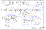
I have been on the look for a +-9v LP filter made from LM13700, tried several but they all didn't sound very good for some reason or another.
Knowing that the Shurthi synth sounds awesome, I looked for one of the filters schematics and discovered that it works with +-5v, so it's a perfect match for Arduino.
I am a beginner in electronics so I am "dissecting" the schematic in order to understand it better and to remove or change the functions that I don't need.

I have a few questions if anyone could help me:
1) Can feedback be replaced with a simpler op-amp (or method) so if I want to do a 2 pole only filter I don't need to use another LM13700? I really don't need CV controlled resonance.
2) The last op-amp (OUTPUT AMP) works like an amplifier of the signal or as a filter? What is the gain of it?
3) If I just remove the "4 POLE PHASE" and get the "RESONANCE FDBK" pin from the "2P OUT", will it work directly as a 2 pole filter?
 

Attachments

  • Shruthi-Analog-SMR4-mkII-v01.jpg
    Shruthi-Analog-SMR4-mkII-v01.jpg
    532.9 KB · Views: 123

I have been on ...

I have a few questions if anyone could help me:
1) Can feedback be replaced with a simpler op-amp (or method) so if I want to do a 2 pole only filter I don't need to use another LM13700? I really don't need CV controlled resonance.
YES
2) The last op-amp (OUTPUT AMP) works like an amplifier of the signal or as a filter? What is the gain of it?
High attenuated input 200/10k followed by high variable I_ controlled gain from CV. The cap just improves phase margin, to prevent spurs >100kHz
3) If I just remove the "4 POLE PHASE" and get the "RESONANCE FDBK" pin from the "2P OUT", will it work directly as a 2 pole filter?
YES, the OTA's are used for current modulated gain

Sure you don't want AM modulators?
 

The compressor in my local FM radio station is an "AM Modulator". The loudness of the background music changes a lot to the beat of the music.
I wish they would turn off the compressor. I have never heard many modern songs the way they were recorded.
 

The 2 circuits you propose to cut use I_CUTOUT and I_GAIN respectively to control the gain or Modulate the Amplitude (AM)

so not just a filter, but a 4stage filtered modulator and output modulator
 

I can make the same sounds and more with a simple 3 bands audio equalizer circuit.
Except this one is voltage controlled. Then why do they use pots to adjust it in the video?
 

Remember, the LM13700 is a transconductance amplifier, the output is a current not a voltage, with that in mind:

"The last op-amp (OUTPUT AMP) works like an amplifier of the signal or as a filter? What is the gain of it?"

The answer would be IC30's Iout * R4
 

I can make the same sounds and more with a simple 3 bands audio equalizer circuit.
Except this one is voltage controlled. Then why do they use pots to adjust it in the video?

Certainly filters can be simplified with Gyrators and OTA's offer good linearity but need to be cascaded for wide dynamic range, the range of which can be controlled by Pot gain and user requirements.
 

The 2 circuits you propose to cut use I_CUTOUT and I_GAIN respectively to control the gain or Modulate the Amplitude (AM)

so not just a filter, but a 4stage filtered modulator and output modulator

Right! Sorry, don't understood. That's the part I don't need. Only the filter.

I can make the same sounds and more with a simple 3 bands audio equalizer circuit.
Except this one is voltage controlled. Then why do they use pots to adjust it in the video?

That's because it can be controlled by the pot directly (signal goes to microcontroller and then sends it to the filter) or it can be programmed to change automatically (again, coming from microcontroller)

Remember, the LM13700 is a transconductance amplifier, the output is a current not a voltage, with that in mind:

"The last op-amp (OUTPUT AMP) works like an amplifier of the signal or as a filter? What is the gain of it?"

The answer would be IC30's Iout * R4

Thanks! It's the first time I hear "transconductance amp" but it makes sense. Told you I was beginner.
 

AM with overlap of modulation rate and sound causes harmonic distortion, which is reduced by feedback cap and mixed externally with unfiltered audio to get full effect.
 

Status
Not open for further replies.

Part and Inventory Search

Welcome to EDABoard.com

Sponsor

Back
Top