Continue to Site

Welcome to EDAboard.com

Welcome to our site! EDAboard.com is an international Electronics Discussion Forum focused on EDA software, circuits, schematics, books, theory, papers, asic, pld, 8051, DSP, Network, RF, Analog Design, PCB, Service Manuals... and a whole lot more! To participate you need to register. Registration is free. Click here to register now.

Help:Canceling the spikes

Status
Not open for further replies.

mohazaga

Full Member level 2
Joined
Aug 18, 2005
Messages
141
Helped
2
Reputation
4
Reaction score
2
Trophy points
1,298
Activity points
2,397
Hi ,,,
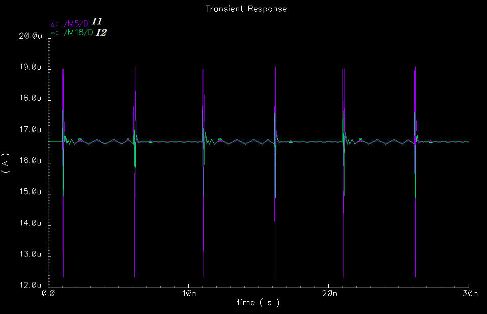
I hope all of you are fine . I use output Current of improved cascode CM as current source. My input to the ckt is diff. pulse (vin2 reverse of Vin1) with 1n delay, 0.1n Rt, 0.1n Ft, 5n Pw & 10n Pp. But the output the is some spikes due of unstable current sources I1 & I2?
So how to make them satble to get stable output voltage?
fig 1 is the ckt

6_1177143776.jpg


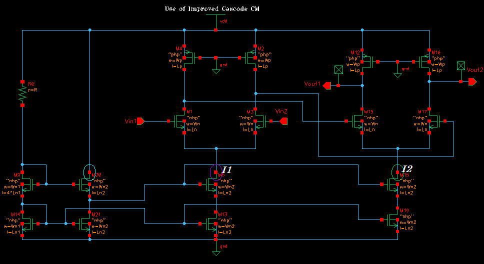
fig 2 is the current I1, I2

9_1177143850.jpg


thankx
 

hi,go throgh cmos book baker&allen.get help of ADS tool.
 

Frist of all, it's not stability. To have stability issues you need a closed-loop system. Your current mirror is a replica-bias mirror, which simply means create an output current source based on matching of components between the Iref and Iout.

Notice that the current through M9 is no way dependent on ANY other voltages/currents except that of the resistor. M20 is probably a very very wide NMOS that takes out one Vt from the bias voltage in order to improve headroom.

What you are probably looking at is switching noise. The inputs to the opamp are probably switching quickly, so the large dV/dT cause charge to couple through the input differential pair, then through the mirrors. So all you are seeing is switching noise. It's really nothing in general to be concerned about.

If you don't want the switching noise of the reference line to affect I2, then you need to isolate the current reference from I2 and I2. You can do that by either having a separate current reference for I2, add filter capacitances, or mirror the reference current around twice before feeding I1. Mirroring aroudn the current reference is probably the easiest. Take a PMOS mirror reference off the M20 line, and then back down to an NMOS reference for I1.

Lastly, you have a lot of numerical noise which may have made you think you have oscillation. You need to simulate at conservative setting, with all the default reltol, Iabstol and vabstol numbers.
Conservative setting is in the transient setup window. The others are in the simulation options, analog options.
 

Hi ,,,
thanks gszczesz , but could u explain h to connect PMOS by the awy u wrote (mirroring around the current reference).
tahnkx
 

Status
Not open for further replies.

Part and Inventory Search

Welcome to EDABoard.com

Sponsor

Back
Top