Continue to Site

Welcome to EDAboard.com

Welcome to our site! EDAboard.com is an international Electronics Discussion Forum focused on EDA software, circuits, schematics, books, theory, papers, asic, pld, 8051, DSP, Network, RF, Analog Design, PCB, Service Manuals... and a whole lot more! To participate you need to register. Registration is free. Click here to register now.

Help a noob identify possibly bad board components

Status
Not open for further replies.

perceptionist

Newbie level 4
Joined
Sep 16, 2011
Messages
6
Helped
0
Reputation
0
Reaction score
0
Trophy points
1,281
Activity points
1,348
Hi all, I have limited knowledge of pc board parts but I am able to carry out a repair if a board component appears visually in need of replacement.

I just bought a used PC gamepad (Saitek P880) which is not being recognized on my PC. I used to own this controller and it was recognized on the same PC with same OS. I have downloaded the current drivers for my OS and the driver install hangs every time not recognizing the gamepad is plugged in as the install wizard requests....

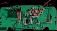
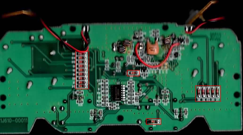
So now with all of that out of the way, I opened the controller finding one of the screws missing indicating someone else had been in there. Below is a scan of the board. In the red box you will see the components I am questioning. I do not know what these are called but I was hoping to attract the attention of any experts here who might be able to tell me what they are called and if these do not look as they should. I found the black portion of these suspect, but then I am limited in my knowledge here.

If needed, I can try to get a more crisp detail scan on the components...

Thanks for any insight...


They look like low power diodes.

Things to try:

Can you verify the board is getting power?

Do you get continuity from each pin on the connector, through the cable, to the corresponding wire emerging inside the housing?

Do you find a disconnected wire to the circuit board?

Do you have a hi power magnifier to search for bad solder joints?
Cracked traces?
Cracked contacts on surface mount components?
Etc.
 
They are indeed low power/small signal diodes, they are supposed to have a thick black line on them to indicate their polarity.
 
Thanks for the replies..

There is a blue LED on the controller which lights up when it is plugged in to a USB port.

I might need to clarify "not being recognized" When I plug it in to the USB port the PC DOES react that something was plugged in by flashing the little USB symbol in the lower right corner (Windows XP 32) but windows concludes this as an "unknown device" but I expected as much until I installed the drivers.. but the driver installation is not seeing the controller... and the driver is the correct one for the OS and controller. This together with trying it on another PC with the same result led me to look into the hardware itself.

I just checked each wire and all 5 of them are getting solid continuity.

No disconnected wires or components found.

I am using a magnifier I got from a junk BMW projector headlamp assy... 5" diameter 1" thick, so it provides me with some nice detail,
hey I gotta be resourceful :)

I did notice one solder joint that was empty on one leg of that large tan part on the board just to the right of center with the red wire curving around it. On the other side of the board where that leg pokes through though is a perfect little pool of solder. This piece does not appear to be damaged or ever removed as it appears to still be factory glued to the board.

Also thanks Hewitson for the description of the low power/small signal diodes. Upon closer examination those are black stripes and not burn marks as I had initially thought.
 

perceptionist said:
I did notice one solder joint that was empty on one leg of that large tan part on the board just to the right of center with the red wire curving around it. On the other side of the board where that leg pokes through though is a perfect little pool of solder. This piece does not appear to be damaged or ever removed as it appears to still be factory glued to the board.
That's a capacitor. Probably not the problem, but it would be worthwihle soldering it in properly.

perceptionist said:
Also thanks Hewitson for the description of the low power/small signal diodes.
Not a problem :)

If you have a multimeter, I would suggest checking that power is reaching that IC. A glowing LED is by no means an indication that all components on the board are receiving power.
 
Does "IC" refer to that capacitor or the Integrated Circuit as a whole? If it refers to the capacitor, I am guessing that I need to set my multi for DC voltage, plug controller to USB, black lead on known ground and red lead to one leg of the capacitor.... if that is correct, my next question before doing so is Does it matter which leg. I want to be careful poking around when this is energized... not so much for safety in this case but I would not want to damage anything by touching the wrong component.
 

Hi,
Your posted picture is not in focus and gives a blurred look. Can you post a High Resolution and properly focused clearer image. To me it seems a Resonator more than a capacitor. Try to see the on board identification text if any.
The circled components in Red are Small signal diodes, most probably 1N4148 or 1N914. Upload a better picture (at least for me) enabling me for better guide line.
 

IC refers to the 14 pin chip in the middle of the board. Get the model number off it and download the datasheet, then you know which pins are for Vcc and ground.

You will not damage anything by touching the "wrong" component, however you must be careful not to short anything together. For example if you accidentally touched the red probe to both Vcc and an I/O pin at the same time, you could do some damage.
 
Awesome thanks for the info. So my initial search has me wondering if together both rows of numbers on the face of the chip are the model# or only the first or only the second row. I could not find an exact match for both rows. The first row only turned up a partial match, and I found an exact match for the 2nd row. That match brought up 10 results but only one of those was made by Texas Instruments like mine.... so I deducted this must be my chip.... How can I tell which pin is #1? The chip on the diagram has the typical little half moon notch designating the top, and mine does not. Mine does have a stripe though, is this stripe a substitute for the notch?

Sorry for all the questions, but I think my success depends on me asking them :)
 

I can't say I've ever seen a stripe used instead of a notch or a dot, but if you look at the chip so that the writing is facing the right way up, pin 1 will be the bottom left. The pin numbers go in a circular pattern, so the bottom right pin will be pin 7 and the top right will be pin 8.

You are right about the second row of text being the chip type (LM something). Which manufacturer you get a datasheet from is irrelevant, they will all have the same pinout (and usually the same specifications).
 

To me it seems a Resonator more than a capacitor.

Yes it looks like a resonator
Resonator2Pin.jpg

How can I tell which pin is #1? The chip on the diagram has the typical little half moon notch designating the top, and mine does not. Mine does have a stripe though, is this stripe a substitute for the notch?

it can be a notch or a dot in pin #1 or even one side of the case cut diagonal in the vertical axis instead of the normal straight vertical etc but the chip that I see in the picture has only 7 pins in one side (not a DIL package) so the first pin from the left is pin 1 (when the pins are faced towards you)

Alex
 

Ok thanks, The shadow in the scan hides one side of my chip... mine has 14 pins so in keeping with the point that mine does have the diagonal cut, I was able to locate the Vcc and Ground pins. I got a reading of 4.86v which I believe seems about right for a USB device.
 

4.86V is within spec for 5V devices.

It suggests that no component is causing a short circuit across the supply rails. The IC might do this if it were fused.

Try testing voltage on the IC pins. See if you get same or different readings. If they're all the same then the IC is probably broken.

When poking around tiny circuitry, I often grip a hatpin with my meter clips. The pinpoint doesn't slide easily, nor is so large as to touch more than one item at a time.

Because as a post #8 says you don't want to bridge across contacts and short them out.
 

Ok so to be clear on my testing with the multi... this is the diagram for my chip...

chip diagram.JPG

My initial test was with Black lead on pin 12 and red on pin 3.

So do the next tests consist of:

Black = pin 4
Red = pin 5

Black = pin 6
Red = pin 7

Black = pin 8
Red = pin 9

Black = 10
Red = pin 11

That seems logical to me but I'm not sure what to do with pins 1, 2, 13, & 14 if anything.

My other thought was to leave the black lead on pin 12 then use the red to test all the + pins.
 
Last edited:

Status
Not open for further replies.

Part and Inventory Search

Welcome to EDABoard.com

Sponsor

Back
Top