Continue to Site

Welcome to EDAboard.com

Welcome to our site! EDAboard.com is an international Electronics Discussion Forum focused on EDA software, circuits, schematics, books, theory, papers, asic, pld, 8051, DSP, Network, RF, Analog Design, PCB, Service Manuals... and a whole lot more! To participate you need to register. Registration is free. Click here to register now.

he same potential difference on both sides of the component

Status
Not open for further replies.

walters

Advanced Member level 2
Joined
Jun 5, 2005
Messages
599
Helped
1
Reputation
2
Reaction score
0
Trophy points
1,296
Activity points
7,730
I just don't understand about resistors and capacitors having the same potential difference on both sides and what they are used for?

Why would you use a resistor or capacitor to have the same potential difference on both sides of the component?
 

I don't quite understand what you're asking. By themselves, resistors and capacitors do not have potential differences between their terminals. It's only when some power source is applied to them that they can have p.d. at their terminals. In other words, it's the way they are used in a circuit that can cause a p.d. between their terminals.

In some parts of a circuit, a particular resistor or capacitor may not have a p.d. between its terminals when the circuit is idle, but does have one when a signal is applied to the circuit.

Perhaps your question will make more sense if you give some example circuit(s).
 

when there is an Open resistor or Open capacitor , when i measure i get the same potential difference on both sides

But the resistors and capacitors are not open internal, they are working and still measure resistance

I just don't understand how there is the same voltage on both sides and no voltage drop or current running through them

Also the values of the resistors or capacitors have different values , so it doesn't matter has the value it

Why would a designer or circuit what a bunch of resistors or capacitor to have the SAME potential difference on both terminals? no voltage drop or current flowing through it but they have the same voltage on both terminals
 

when there is an Open resistor or Open capacitor , when i measure i get the same potential difference on both sides

how can you measure both sides if its open from one side if you have electrolyte capacitor then its negative must be grounded to take effect of capacitor in circuit .
 

No, I understand when there is an internal open inside a component, that it will have the same potential difference on both sides of it and no current flowing through it because there is a break inside

I don't understand how a normal operating resistor or capacitor that is working can measure good but has the same potential difference on both sides of it , no voltage drop, no current flowing through it.

It acts like there is a break or an internal open inside of the component but there isn't

That's what i don't understand
 

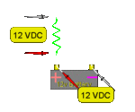
hope you measuring them as shown in pics and if i am not getting your question wrong you are saying that when you measure voltage as shown in pic you have same voltage at both terminal correct me if i am wrong
 

Attachments

  • resvd01.gif
    resvd01.gif
    3 KB · Views: 90
  • resvd02.gif
    resvd02.gif
    5.8 KB · Views: 84
  • resvd05.gif
    resvd05.gif
    3.7 KB · Views: 95

Yes I measure with my DVM across the component, either its a resistor or capacitor

If a PCB board circuit has 50 resistors and capacitors, 30 of the Resistors and capacitors have the same voltage on both pads/terminals/sides, what are they used for?

Because Mostly there is a voltage drop around resistors and capacitors

But there is also resistors and capacitors that have NO voltage drop or current flowing through them , but they have the same voltage on both sides/pads/terminals around the component
WHY? what are they used for?

---------- Post added at 08:37 ---------- Previous post was at 08:23 ----------

At work , I take a good PCB board that has passed all the test

1.) I measure the voltage across each resistor and capacitor with my DVM and write those values down
2.) only 5 out of 100 resistors only have voltage drops
3.) The other 95 resistors have no voltage drop or current flowing through them, But the resistors have the same potential difference, with the same voltage on both sides of them

The only thing I can think of is that those resistors with the same potential difference with the same voltage on both sides are either controlled by MOSFETS or digital switch , The resistors seems like they are in a idle state? maybe they are waiting for a High Or Low signal?
 

Your first error is that you did not mention that you're talking about components already installed on a PCB and you measured the voltage while it's powered on. The second error is in assuming that a resistor or capacitor must have voltage across it at all times to do some useful work. The third error is the assumption that such a voltage must be DC that can be measured with a DVM.

In many parts of a circuit, current passes through a component, causing a measurable voltage drop, only when there's an appropriate signal driving the system. Even when there's a signal, some sections may have only millivolts or microvolts across them. At some points in the circuit, the signal may be a symmetrical AC so that a DVM on DC range will display zero even when there's a signal.

The only thing I can think of is that those resistors with the same potential difference with the same voltage on both sides are either controlled by MOSFETS or digital switch , The resistors seems like they are in a idle state? maybe they are waiting for a High Or Low signal?
This is partially true. But since your question is of a very general nature rather than about a specific circuit, don't think only in terms of digital high-low levels. There's an unlimited number of voltage levels possible in analog circuits.

Even in a digital circuit, the voltage across a component may be a very short pulse - for example, a 1 usec pulse repeated at 100 Hz. In such a case, the duty cycle of the pulse is 0.0001 and your DVM will measure practically zero. There are two reasons for this:

The first reason is that a 5V pulse at 0.0001 duty cycle is only 0.5mV average. The second reason is that your DVM is probably not fast enough to take a reading during such a brief pulse.
 
Last edited:

Status
Not open for further replies.

Part and Inventory Search

Welcome to EDABoard.com

Sponsor

Back
Top