waswart
Newbie level 3

- Joined
- Jan 13, 2015
- Messages
- 3
- Helped
- 0
- Reputation
- 0
- Reaction score
- 0
- Trophy points
- 1
- Activity points
- 39
Hi,
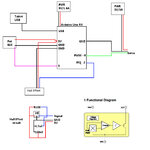
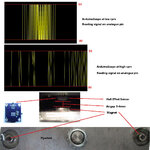
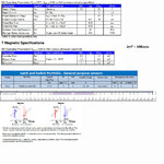
I am having problems with a Melexis US1881 Hall Effect sensor (latch type) which is used to measure rpm. It is used with an Arduino Uno R3. I have attached some images showing the setup and extracts of the datasheet.
From a cold start, it works correctly initially but then starts degrading (not latching correctly) after typically twenty minutes and this gets worse as time goes on until it almost doesn't latch at all (except at very low rpm). When started again soon after it would degrade sooner (say after 8 minutes) then again after 5 minutes etc. It would still latch correctly at very low rpm, even when in degraded state.
In typically use the rpm would be about 60Hz and the sensor is rated for 10KHz.
From a layman's point of view, it seems it is a problem of a component degrading over time (or being saturated over time) to the point where it no longer functions correctly.
The setup is as per the images.


Things I have tried:
1. Magnets: I have replaced the magnets (rare-earth magnets which are quite strong) as the fly-wheel gets quite hot (it can get up to 70-80 degrees Celsius) as it could be possible that heat affects the magnetic strength. Have also mounted the magnets on wood to reduce heating up of magnets which has not solved the issue.
2. Replaced the Hall Effect sensor several times in case it was damaged.
Possibilities:
1. Magnetic environment: there are other magnets in the housing behind the flywheel (it is a magneto trainer) mounted on the inside of the housing with the Hall Effect sensor magnets mounted on the outside of the flywheel.
2. I am not too clear on the internal workings of the sensor and if the problem is related to output voltage saturation or the magnetic specifications for the operating, release and hysteris. Perhaps the magnets are too strong or too close, and perhaps could have a cummulative effect?
Links to datasheets and application notes:
https://www.melexis.com/Hall-Effect-Sensor-ICs/Hall-Effect-Latches/US1881-140.aspx
I am very much a hobbyist and any comments/suggestions as how to proceed would be appreciated.
Thank you
I am having problems with a Melexis US1881 Hall Effect sensor (latch type) which is used to measure rpm. It is used with an Arduino Uno R3. I have attached some images showing the setup and extracts of the datasheet.
From a cold start, it works correctly initially but then starts degrading (not latching correctly) after typically twenty minutes and this gets worse as time goes on until it almost doesn't latch at all (except at very low rpm). When started again soon after it would degrade sooner (say after 8 minutes) then again after 5 minutes etc. It would still latch correctly at very low rpm, even when in degraded state.
In typically use the rpm would be about 60Hz and the sensor is rated for 10KHz.
From a layman's point of view, it seems it is a problem of a component degrading over time (or being saturated over time) to the point where it no longer functions correctly.
The setup is as per the images.


Things I have tried:
1. Magnets: I have replaced the magnets (rare-earth magnets which are quite strong) as the fly-wheel gets quite hot (it can get up to 70-80 degrees Celsius) as it could be possible that heat affects the magnetic strength. Have also mounted the magnets on wood to reduce heating up of magnets which has not solved the issue.
2. Replaced the Hall Effect sensor several times in case it was damaged.
Possibilities:
1. Magnetic environment: there are other magnets in the housing behind the flywheel (it is a magneto trainer) mounted on the inside of the housing with the Hall Effect sensor magnets mounted on the outside of the flywheel.
2. I am not too clear on the internal workings of the sensor and if the problem is related to output voltage saturation or the magnetic specifications for the operating, release and hysteris. Perhaps the magnets are too strong or too close, and perhaps could have a cummulative effect?
Links to datasheets and application notes:
https://www.melexis.com/Hall-Effect-Sensor-ICs/Hall-Effect-Latches/US1881-140.aspx
I am very much a hobbyist and any comments/suggestions as how to proceed would be appreciated.
Thank you


