Continue to Site

Welcome to EDAboard.com

Welcome to our site! EDAboard.com is an international Electronics Discussion Forum focused on EDA software, circuits, schematics, books, theory, papers, asic, pld, 8051, DSP, Network, RF, Analog Design, PCB, Service Manuals... and a whole lot more! To participate you need to register. Registration is free. Click here to register now.

Half bridge SMPS capacitor capacitance question

Status
Not open for further replies.

Salvador12

Full Member level 4
Joined
Jul 16, 2014
Messages
211
Helped
3
Reputation
6
Reaction score
7
Trophy points
1,298
Activity points
4,001
I wanted to add a better quality capacitor to my working half bridge SMPS but I was wondering given frequency of switching stays the same and is controlled by the IGBT/mosfet driver IC.
What would change if I changed the capacitance value of the half bridge transformer capacitor ? Say i increased it from the existing 1uF to say 2.2uF.

Would that cause a larger current on each half cycle as the cap gets charged and discharged through the switches?

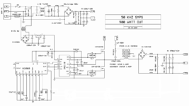
I attached the schematic.
 

Attachments

  • 50khz-4n25-sg3525-smps-ir2110-smps-900wpower-supply without feedback.png
    50khz-4n25-sg3525-smps-ir2110-smps-900wpower-supply without feedback.png
    127.9 KB · Views: 307

For a general rule yes, the cap value has a lot to do with how much current goes through the transformer.

Picture if you install a tiny value. It charges quickly after each switch-On, then it blocks current. As a result little current gets through in either direction.

Increasing cap value tends to increase current. Of course there's a point where too much power goes through the transformer causing it to saturate, or overheat, etc.
 

That 1uF cap in series with primary is the DC blocking capacitor, which prevents flux walk in the transformer....and thence prevents uneven voltages on the split capacitors......it shoudl be big enough that it doesnt impeded the transformer current waveforms and preferably no bigger...if it is too big , then you may still get some flux walking at first, until the series capacitor gets charged up.

You have no primary overcurrent protection, that is the worrying thing....you need really a current sense transformer in there.

If you have a Current sense transformer in there, and your split caps can tolerate the total rail voltage, then you can make the series capacitor as big value as you like.......but preferably not too big, as you want it to charge up in response to uneven switching in the fets....ie due to flux walk or split rail cap voltage imbalance....and by charging up, it will avert the imbalance in the split rail caps.

You dont want to loose too many volts in the primary coil, so pick a cap that will just charge up to a few volts in either direction due to the max power transformer current.

Get a sim going as attached in free LTspice to look into it a bit.

Also, the resonant frequency of that cap with the txformer leakage inductance must not be higher than the switching frequency.....preferably.

In the Half Bridge folder of the attached smps course there is some stuff on half bridge

SMPS course_little folders
https://drive.google.com/file/d/1WvElhDNfHI0EBei4rouSNEdWWTO1oCtJ/view?usp=sharing

So anyway, if the Half bridge goes imbalanced, then that nice series capacitor will charge up in such a direction, that it opposes the build up of imbalance voltage on the split rail caps (rail splitting caps)...and thus it will balance it all out nice for you.
___--___

What you can do, is run a copy of your schem on the ltspice sim......the sim wont go unblanced...so do it with and without the series cap...and settle for that smallest value that doesnt distort the current waveform in the primary...but also bear in mind the above resonance issue.
 

Attachments

  • Half Bridge _Voltage Mode _Full wave voltage doubler input.zip
    3.8 KB · Views: 151
Last edited:
the current will barely change, as it determined by the load.
But doesn't the transformer primary and small cap in series form a series LC? I think they do, in that case the transformer primary could have higher amperage through it if the switch frequency matches the resonant frequency of the series LC.

I guess a half bridge is best run off/away from this series LC resonance as at it the load of the transformer presents itself as a short to the switches?
 

The resonant frequency of the Pri coil and the series cap should be way below the switching frequency in a hard switched half bridge converter.
 

I'm running a simplified simulation. An op amp automatically detects the LC resonant frequency and switches 300V back-and-forth through the primary.

Secondary spec 10:1 step-down with a 22 ohm load. Resonant action creates waveform amplitudes rising to several kV. Power throughput is so great as to be utterly unrealistic.

It's an easy bet your schematic does not operate as an LC resonant converter.
 

The capacitor value suggests that the circuit is designed as series resonant LC converter. But without knowing transformer Ls and Lh parameters, it's just a guess.
The resonant frequency of the Pri coil and the series cap should be way below the switching frequency in a hard switched half bridge converter.
Why would you operate an unregulated 900 W converter hard switched? And which resonance are you referring to?
 

As it is an half bridge you do not need the 1uF / 400V blocking cap - as the rail splitting caps perform this function ( DC blocking ) - what would be beneficial would be the osc ramp powered from Vin - this will give you line feed forward and very much better dynamics - as would ave curr mode control ...
 

Why would you operate an unregulated 900 W converter hard switched? And which resonance are you referring to?
I see your point, though this is what the OP is doing, and sucessfully by the sounds of it, ....its a plain voltage mode controlled half bridge.
I am of the undertsanding that hard-switched and 900W and 50khz is fine for offline smps at 900W.

And which resonance are you referring to?
....that the resonant frequency between the series cap and the primary coil (LMag) should be well below the f(sw).

You often see the series cap in half bridge circuits...i think its just in case of output short cct.
With the half bridge, it will flux walk if in current mode, and the rail splitting caps will get unbalanced...this doesnt happen in voltage mode....but in voltage mode, when it gets overloaded, then (if there is a peak current limit as there should really be)....it acts in peak current mode operation, and the rail splitting caps will get unbalanced. Isnt that series cap there so that the unbalancing that happens in "voltage-mode-and-overloaded" doesnt happen quite so badly...i believe it is.
 
Last edited:

Why would you operate an unregulated 900 W converter hard switched?
This is a good question though....its turn off switching losses which make hard-switched a little on the undesirable side when it comes to hard switched and offline.........the alternative is LLC or PSFB.....But PSFB only gets a soft turn off if you use a big-ish capacitor across vds of the fet......and if you do that you have to know what you are doing.....most PSFBs have no such capacitor, and simply dont reap anywhere near the full benefit of a PSFB....they may aswell just have used a hard switched full bridge........which of course has a nice turn on snubber by way of the leakage inductance.,
 

@FlyBack - current mode is not a definitive term - ave curr mode induces no flux walking and allows fast output dynamics

Peak current mode is the one that will shift the cap midpoint if too much is used. Some peak current mode can be applied as it acts very similarly to volt feed forward of the Vin to the osc ramp.
 
Thanks, its surprising average current mode isnt used more often in half bridges. After all, the half bridge is a great way to get 100-400W power levels....since AYK its txfrmer only "sees" half of the vin, so dB can be well limited with a small core...also, i would have thought ave currnt mode is a bit like the PFC way of doing it........you get an external voltage error amplifier to adjust the internal current error amplifier's set point so as to regulate the whole thing.........and i would imagine you would use just say a CST, and filter the output pulses of it to give your ave currnt signal.......

...But anyway, to really satisfy the OP, that series cap is not needed, as you say, in the pure voltage mode case, (or ave curr mode case) , but is needed if peak current mode is used , without enough added slope ramp. The amounf of added slope ramp that is needed, to allow non use of the series cap, is not fully known and certainly not publicly published, so people will end up using the series cap anyway, i would have thought....also, it is probably worth using it to give some short circuit output proofing.

The thing is, does use of the series cap totally alleviate rail cap imbalance in cases of use of pure current mode control? (with no added slope ramp). I hope the OP forgives the qu's , it was thought they may be useful to them.......their original qu has been fully answered i believe.

So anyway, what we can say to tthe OP is that the smaller the series cap , the better. (low uF value). However, is must not be so small that it seriously alters the waveshape of the current pulses. The smaller series cap woudl give better outptu short cct protection.....Also, the smaller series cap woudl also give better rail cap balancing in cases where peak current mode is used...however, the OP is not using peak currnt mode, so doesnt need the series cap anyway (at least not for cap balancing).
 
Last edited:

Thanks, in that case, the point of the series cap must only be for "short circuit output" proofing(?)

Also, the series cap could be for helping to balance out the situation when eg the top rail split cap is say 10% more in capacitance than the bottom rail splitting cap......in which case, indeed the series cap should be as small in Faradic value as possible.

Raymond Mack's book "Demystifying switch mode power supplies", on page 160, states that for a half bridge, we either need a capacitor in series with the primary, or a Balancing winding, which keeps the voltages on the rail-splitting caps equal.
.....Mack states that half-bridge can be done without a balancing winding or series capacitor, but only if the rail splitting caps are the output caps of a mains voltage doubler rectifier...(because then, he says, we get a hard centre point voltage)
 
Last edited:

Pretty certain the full reason for the series cap in half bridge is in this book by Billings + Morey
..my copy is 90 miles away in my lockup. (last time i went to the lockup, i got fined £190 for forgetting to pay the Dartford tunnel toll on time). Anyone with the book, very grateful for view of the page. It will help OP to know what this cap is for i am sure.
 

A hard centre point is a different kettle of fish altogether - as you then effectively have 2 stacked volt sorces. - as you are no longer "rail splitting" with the caps - intuitively if you pull assymetric currents out of a rail splitting capacitive arrangement - its not long before the mid point moves quite a way ...
 

Thanks, i see your point, though Mack, in his book, recomends a series capacitor for balancing the rail caps, when not using the "hard centre point" method.
The idea of the series cap, seems to be to counteract the unequal voltage of the rail splitting capacitors...ie, it develops a voltage which "opposes" the unequalness of the rail split caps voltage.
 

" Mack, in his book, recomends a series capacitor for balancing the rail caps, when not using the "hard centre point" method.
The idea of the series cap, seems to be to counteract the unequal voltage of the rail splitting capacitors...ie, it develops a voltage which "opposes" the unequalness of the rail split caps voltage. "


I should like to see this - as it appears to be incorrect at 1st glance.
 

Status
Not open for further replies.

Part and Inventory Search

Welcome to EDABoard.com

Sponsor

Back
Top