Dale Gregg
Junior Member level 3

- Joined
- Jul 23, 2013
- Messages
- 29
- Helped
- 2
- Reputation
- 4
- Reaction score
- 2
- Trophy points
- 3
- Location
- Leeds, United Kingdom
- Activity points
- 263

Hi, I'm simulating my inverter but finding a efficiency of 35% across the switching circuit. I calculated the switching voltage as 35V but this produces a Vpeak of 18.5V and 65A at the output.
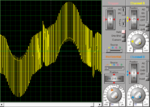
I bypassed the filter and connected the oscilloscope as shown above and this is the output,

The peak pulses are at about 20V and then either side there a drop. The positive cycle starts at the same level and then drifts upward as shown.
I adjusted the switching voltage down to 20V,

This gives a much clearer 28V pulse which was my target peak voltage.
Could any one help me under stand why this is happening?
The carrier frequency is 15.6KHz, driver voltage is 23V, target current is 100A on to a 200mΩ load.
Vsw=Psw/Isw
Psw=Po/eff
Po=Vp*Io (peak)
Vp=(Io*Ro)/0.707107
Vp=(100*0.2)/0.707107=28.28 (max DC=0.98) 28.28/0.98=28.86
Po=100*28.86=2886
Psw=2886/0.82=3520
Vsw=3520/100=35.20V
Have I made a mistake here, as Im getting my target results from 20V? Any help would be great.
Regards,
Dale
Last edited:


