Continue to Site

Welcome to EDAboard.com

Welcome to our site! EDAboard.com is an international Electronics Discussion Forum focused on EDA software, circuits, schematics, books, theory, papers, asic, pld, 8051, DSP, Network, RF, Analog Design, PCB, Service Manuals... and a whole lot more! To participate you need to register. Registration is free. Click here to register now.

H-bridge simplification

Status
Not open for further replies.

rocky79

Member level 5
Joined
Sep 20, 2010
Messages
83
Helped
1
Reputation
2
Reaction score
0
Trophy points
1,286
Activity points
1,903
Hello all,

I am building an economical H-bridge circuit using minimum component counts, I found this schematics online that I want to simplify little bit, where I thought I wouldn't need trans Q6 and the 2.2K ohms resistor but instead drive the PMOS AND THE NAND GATE directly from the microcontroller pin.

That should work, unless I am missing something. Your input is appreciated.
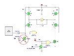
H-BRIDGE.jpg
 

I am building an economical H-bridge circuit using minimum component counts
This won't work (very well). Firstly, you've got a pullup to 12V on your PIC - not very nice.
Secondly, it's not a good circuit anyway.

A H-bridge is never economical in terms of component count if you try to implement in discrete components.

You're better off with an off-the-shelf IC - I don't use them, but L293 or whatever.

EDIT: Also, your top of the bridge will never fully turn off. If you really want to go down the road
of using this circuit, then you need to leave the Q6 in place.
 
Last edited:
You're right, didn't pay attention to the 12v. I see, I will leave Q6 in place.

Secondly, it's not a good circuit anyway.
Beside leaving Q6 in place, why it isn't a good circuit? I am looking to do a simple full forward and full reverse, no PWM is involved.
 

Status
Not open for further replies.

Similar threads

Part and Inventory Search

Welcome to EDABoard.com

Sponsor

Back
Top