nadre25
Member level 3
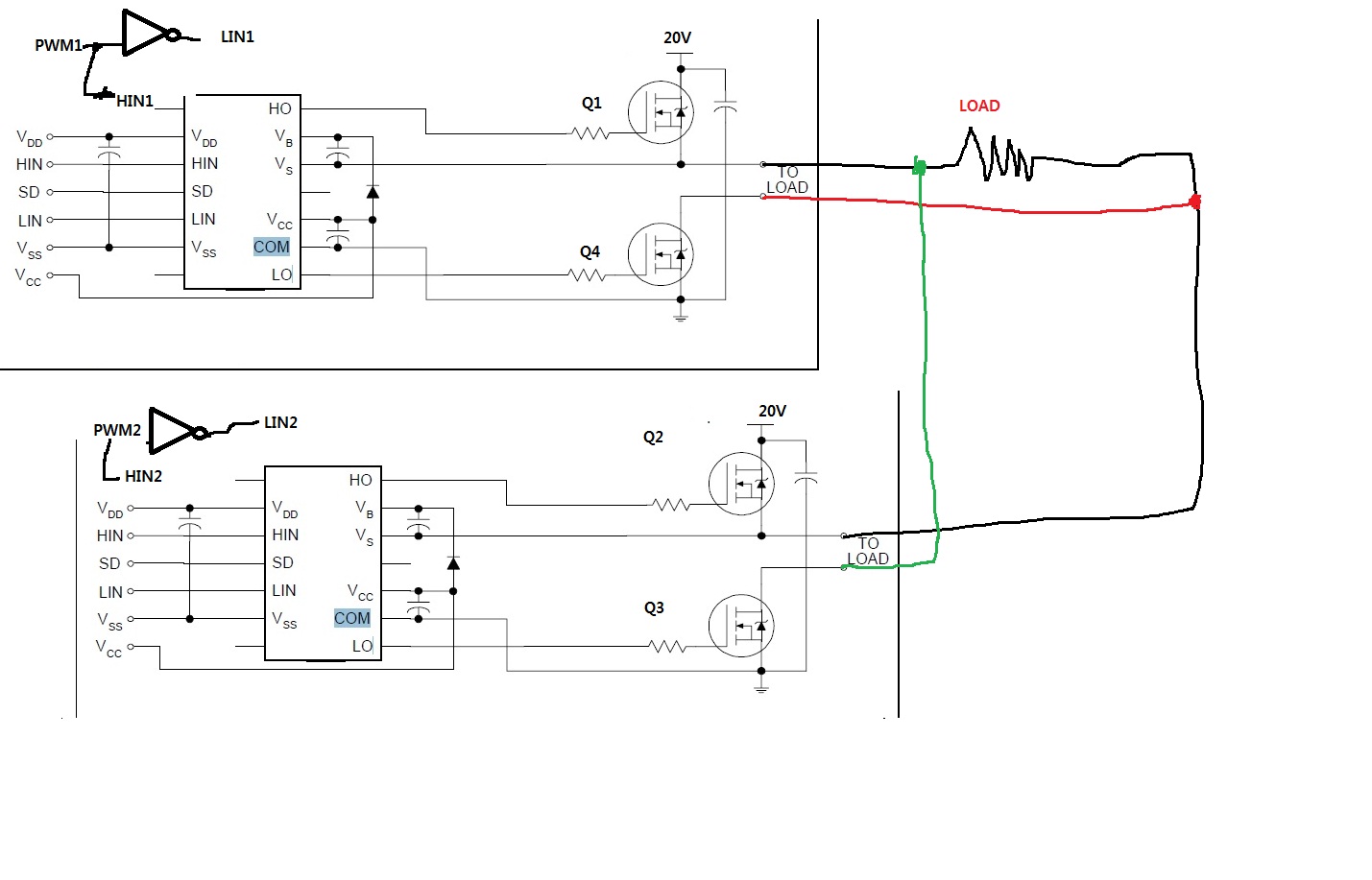
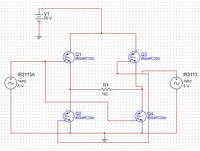
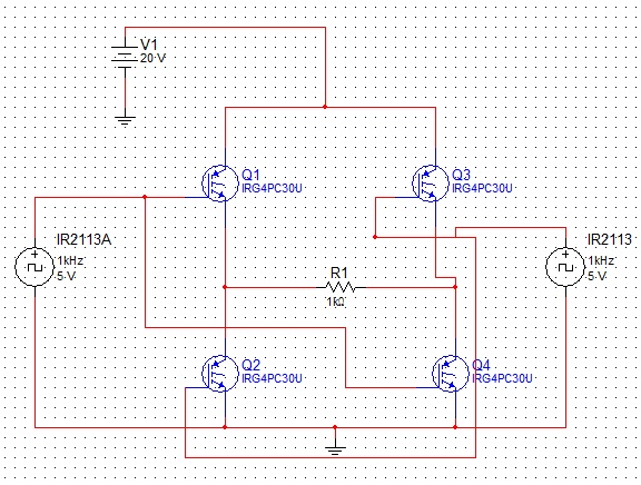
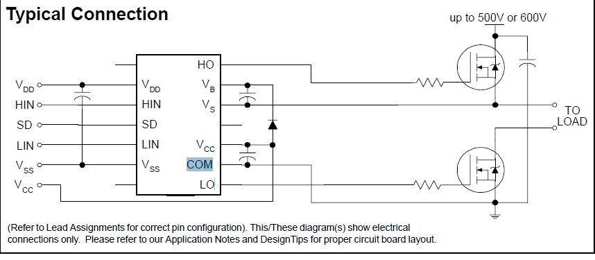
Hi we are having a problem with our H-Bridge. We used an IGBT and IR2113 as its gate driver. We already saw another post but for some reason we can't comment on it... so we made a new one.
Our Voltage Input on the H-Bridge is 20V
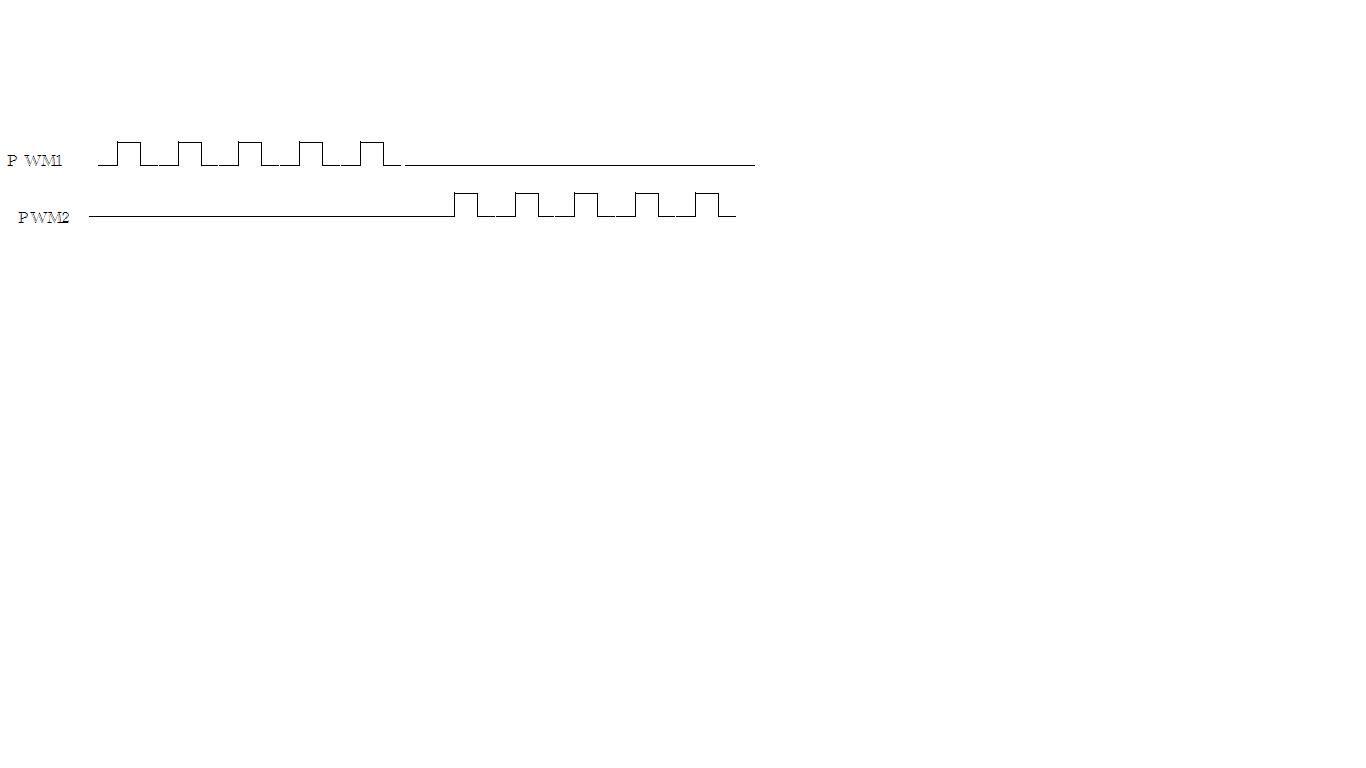
The signal voltage source just represents our input on the gates, its PWM driven. the PWM comes from our microcontroller, we programmed it in such a way that at a certain time ONE pair of IGBT'S are ON and the other pair is OFF
Problem: The 20V source is shorting once we connect it to the circuit. Q1 and Q4 are the transistors that turns on at the same time. and Q2 and Q3 are the other pair.
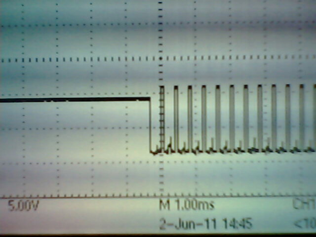
When we test it as a Half bridge by using Q1 and Q4 we get our desired output which is a square wave and same when using Q2 and Q3 only.
We really plan to use this on a motor to control it but for testing we are just using a resistor.
Are we lacking something?
Comments are appreciated. Thank You
Our Voltage Input on the H-Bridge is 20V
The signal voltage source just represents our input on the gates, its PWM driven. the PWM comes from our microcontroller, we programmed it in such a way that at a certain time ONE pair of IGBT'S are ON and the other pair is OFF
Problem: The 20V source is shorting once we connect it to the circuit. Q1 and Q4 are the transistors that turns on at the same time. and Q2 and Q3 are the other pair.
When we test it as a Half bridge by using Q1 and Q4 we get our desired output which is a square wave and same when using Q2 and Q3 only.
We really plan to use this on a motor to control it but for testing we are just using a resistor.
Are we lacking something?
Comments are appreciated. Thank You
")