Continue to Site

Welcome to EDAboard.com

Welcome to our site! EDAboard.com is an international Electronics Discussion Forum focused on EDA software, circuits, schematics, books, theory, papers, asic, pld, 8051, DSP, Network, RF, Analog Design, PCB, Service Manuals... and a whole lot more! To participate you need to register. Registration is free. Click here to register now.

guard trace with via in ads

Status
Not open for further replies.
hi ......
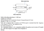
i am solving one paper that paper gives the guard trace to reduce the crosstalk.......
i have attached the Schematic diagram
i have to simulate that diagram in ADS can you help me pls ..........

Please help me to solve this paper .......please please.......

in that diagram their use the microstrip line
Picture1.png

Picture1.png
Thanking for your replay.........
By gopinath
 

OK, Now your question is clear.
You can not simulate this structure in schematic.
You have to simulate it in momentum.
1) Define your substrate in momentum.
2) Draw your microstrip line on say cond layer. (also you need to draw the guard ring on this cond layer)
3) draw your vias on a separate layer.
4) In the create/modify substrate -> layout layers tab, map your cond layer as a strip and also map the layer that you had drawn your via on as via layer.
5) simulate S parameters.

If you want to get accurate results, enable edge-mesh and also increase meshing frequency.
 
hi .......
thank you, now am clear still i have one doubt ...how can i draw the guard ring can u explain.....
can u send the Momentum File for this, if u have time ..please help me......my mail id is gopigopinath10@gmail.com

Thank you for your Immediate reply .thank you so much.......
by
Gopinath
 

It seems that your not familiar with momentum
Read the document from ADS about momentum: mom.pdf and it's in the installation directory of ADS.

Anyway I only drew your layout on momentum, the dsn file is in the MSL.rar. copy and paste this dsn into your networks.
Then open it.

If dimensions are not correct, please change them.
 

Attachments

  • 11.rar
    1.3 KB · Views: 57
  • MSL.rar
    1.4 KB · Views: 57

thank you so much ....
i can change the dimensions......
thanks ........
if i have any help can i ask to u ......
can u send ur mail id .......
thanking you

---------- Post added at 07:18 ---------- Previous post was at 07:12 ----------

thank you so much ....
i can change the dimensions......
thanks ........
if i have any help can i ask to u ......
can u send ur mail id .......
thanking you
 

You are welcome

You can ask your question in the forum, so others also can help you or they can learn from our posts. That's what forums are for
Or you can send me a private message in the forum
 
hi ...
I simulate the file i got some errors.....can you explain/.........

in Substrate creation Layout Layers Contains
Freespace
Strip
FR4
Ground

Here Where i add the via in the layout layer .........
 

I had mapped the via in the file that I uploaded in here.
Via should be mapped to FR4 layer.

Did you set the frequencies?
Also I have drawn the layout on the self-defined layers: Topmetal and Topvia
change them to cond and cond2 or whatever layer is available in your project.
 
hi i have simulate the file i have following errors .

Port number 4:

one or more ports in the layout were drawn on layer 0 ("default").
Layer 0 is not a valid layer for Momentum layouts !

Port number 3:

one or more ports in the layout were drawn on layer 0 ("default").
Layer 0 is not a valid layer for Momentum layouts !

Port number 2:

one or more ports in the layout were drawn on layer 0 ("default").
Layer 0 is not a valid layer for Momentum layouts !

Port number 1:

one or more ports in the layout were drawn on layer 0 ("default").
Layer 0 is not a valid layer for Momentum layouts !

please .........
solve the errors..step by step simulation is i need ...........
please help me........
 

These errors are happening because as I told you in the previous post my drawn layers don't match with your project's layers.
Please study some tutorials about momentum

Anyway I have changed the layers in the attached file in here.
Change the substrate thickness to your substrate's thickness.
 

Attachments

  • MSL1.rar
    1.5 KB · Views: 57

hi i have simulate the Paper ......i got a exact result thank you ......

---------- Post added at 09:47 ---------- Previous post was at 09:19 ----------

hi ..........
Can i Draw the serpentine trace.....in ADS .....How can i draw the Structure of Serpentine trace...in ADS...
Do you know the Spice Simulation Software..........
thanking you .....
gopinath
 

Of course you can simulate any planar structure in momentum. steps are exactly like your previous project.
My suggestion: read a tutorial document about momentum
 

do you have a Tutorial document about momentum..........
Do you have it Please upload it....
if you have a diagram of the serpentine trace send it me..........please......


gopinath
 

For serpentine trace google it, like I did and found it.

For momentum I have uploaded it
 

Attachments

  • mom.rar
    3.1 MB · Views: 156

ya thanking you........
thank you so much...........
if you have serpentine structure in the microstrip line please upload it........
thanking you....

Really u help so much thanking you......
Please upload the serpetine structure in microstrip upload it................
 

Sorry I don't have it.

read the document and start to lay out your structure. If you have problem then I can help.
 

hm ....i am studying .........that mom.....
do you know about the CST MWS......

gopinath
 

CST MWS is a good software for full-wave simulation but for planar structures I prefer momentum
 

Status
Not open for further replies.

Part and Inventory Search

Welcome to EDABoard.com

Sponsor

Back
Top