player80
Full Member level 2
Hi,
I'm doing some Audio application, now I discovered with a cheap DVD Player when I connect the Line-Out to the Line-In Jack of my application the audio chip might reset.
The problem is that the chip requires 3.3v on an EN pin if it drops below it might trigger a reset.
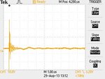
Now I checked the voltage on the shielding of the DVD Player, the scope says around 130 Volt (using the ground from the target application). As far as I read up on the internet this is a common case and very likely caused due induction on the AC adapter of the DVD player (I asked my friends to check their consumer electronic players they also confirmed that the voltage is usually >100V on the shielding, the brand does not matter Sony, Panasonic, etc. they all seem to have a similar behaviour).
If everything is already connected before booting up before initializing the audio chip everything is fine.
Does anyone have an idea what can be done here?
An audio transformer is a possible solution, but I wonder if there's any way to protect my circuit from such inrush shock shock situation?
It doesn't really matter where I touch the shieldings of the 2 devices, it happens easier if I do it at the connector, but also happens if I just touch the grounding of the dvd player on the grounding of the AC adapter of my application.
According to the scope, the Pk-Pk with the audio transformer is 106V (RMS 27V), without audio transformer 280V (RMS 91V)
The current must be small otherwise I wouldn't be able to write this!
Last edited:
