Continue to Site

Welcome to EDAboard.com

Welcome to our site! EDAboard.com is an international Electronics Discussion Forum focused on EDA software, circuits, schematics, books, theory, papers, asic, pld, 8051, DSP, Network, RF, Analog Design, PCB, Service Manuals... and a whole lot more! To participate you need to register. Registration is free. Click here to register now.

Glitches at gate signal output of IR2110

Status
Not open for further replies.

sabu31

Advanced Member level 1
Joined
Jan 28, 2011
Messages
446
Helped
12
Reputation
24
Reaction score
13
Trophy points
1,298
Activity points
5,153
Hi

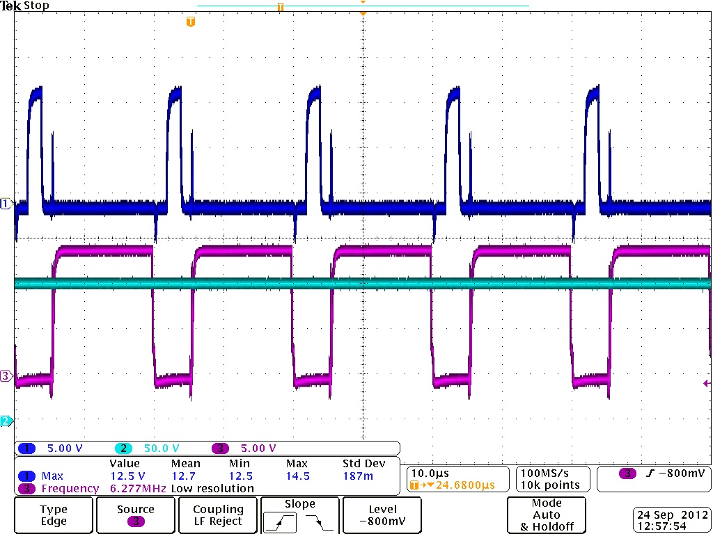
I am getting glitches in the gate of the H-Bridge inverter, the glitch magnitude increases with dc link voltage upto a limit of 6-7 volts.


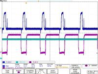
Similar glitch is observerd at the optocoupler(6n137) ouput which goes to the driver (IR2110 ) which drives the inverter. How do we avoid this glitch.

Thanking you.
 

Since you are seeing the glitch on the input to the driver, then the problem is not the driver, it's somewhere else. My guess is you've got some layout issues. Switching the MOSFET gates requires very large current transients, and these transients might be coupled back to the rest of your circuit through ground returns. Look closely at your layout. Also, verify that your supply is solid and is not being sucked down by those transients.
 

hi,
you got a problem with the glitches internally you can also avoid that by adding high capacitance in the output to discharge the excess glitches that are coming. by going through various stages of filtering we can get clear output.

best regards
bala krishna
 

hi,
you got a problem with the glitches internally you can also avoid that by adding high capacitance in the output to discharge the excess glitches that are coming. by going through various stages of filtering we can get clear output.

best regards
bala krishna

Sorry, but that's a terrible idea. The whole point of the driver is to supply a very fast, high-current signal to the gate of the MOSFET. The gate of a MOSFET is capacitive which is why the high current drive is needed. By adding even more capacitance, you are now diverting current that could be used to charge the gate. This could result in overheating the MOSFET.
 

Sorry, but that's a terrible idea.
Not necessarily... if the "glitch" is due to miller capacitance, then adding capacitance to the gate of a FET is a legit way to avoid dv/dt induced turn-on. It's certainly not the most optimal solution (reducing the impedance of the gate driver is), but it's always one option. But he should try various other methods first, including making the measurements with differential probes, and decreasing parasitic inductance.
 

The OP already stated that the glitches appear on the input to the driver, so the correct approach is to find the source of those; they almost HAVE to be from some ground bounce or some other coupling.
 

Yes, I missed that part of his post, my mistake. Yes it's likely that it's a problem with the measurement setup, I have a hard time believing that pulse actually exists on the driver input.
 

Since you are seeing the glitch on the input to the driver, then the problem is not the driver, it's somewhere else. My guess is you've got some layout issues. Switching the MOSFET gates requires very large current transients, and these transients might be coupled back to the rest of your circuit through ground returns. Look closely at your layout. Also, verify that your supply is solid and is not being sucked down by those transients.

Thanks for the replies. I had put decoupling capacitors of .1u and 10u at the Vcc and Ground of the optocoupler and driver. Is it possible that the glitch is due to the capacitance between the LED and Collector within the optocoupler.
Thanking you.
 

Status
Not open for further replies.

Similar threads

Part and Inventory Search

Welcome to EDABoard.com

Sponsor

Back
Top