Continue to Site

Welcome to EDAboard.com

Welcome to our site! EDAboard.com is an international Electronics Discussion Forum focused on EDA software, circuits, schematics, books, theory, papers, asic, pld, 8051, DSP, Network, RF, Analog Design, PCB, Service Manuals... and a whole lot more! To participate you need to register. Registration is free. Click here to register now.

Getting accurate temperature reading from sensors

Status
Not open for further replies.

I14R10

Full Member level 3
Joined
May 31, 2015
Messages
185
Helped
0
Reputation
0
Reaction score
0
Trophy points
1,296
Activity points
2,750
Hi

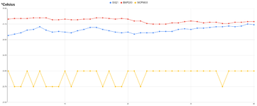
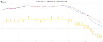
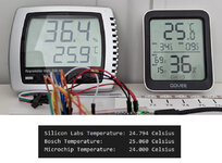
I've been playing with MCP9808 temperature sensor. In the datasheet it says its accuracy is under +/- 0.25 degrees C, and can be around +/-0.1, but It doesn't seem that way to me. I made two identical boards, each using one 9808 sensor, and compared it to my weather station reading. Now, my weather station is also not that accurate, it's WS-2300 model which costs about 70 euros for temperature and humidity sensing unit. But the problem is that one 9808 reads on average 0.5-0.7 degrees higher than my weather station, and the other reads about the same, or slightly lower. From the datasheet I expected them to be a lot closer. What I got from these two 9808 is that they can be around 0.7-0.8 degrees apart on average. And it shouldn't be that large difference between different chip readings.

I'm also looking at TMP117 sensor, which too claims that it has accuracy around 0.1 degree C, and it is quite more expensive than MCP9808, which sounds good.

So my question is, can I trust datasheets at all? Is it better to buy one relatively expensive sensor, or buy 5-10 cheaper ones, like 9808 and average their results? Do you have any sensor that you would like to recommend?
 

Hi,

You can trust datasheet specifications.
But:
* be sure you did not buy a fake copy device
* strictly follow the layout consuderations
* strictly follow the thermal consuderations
* follow power supply considerations
* and timing considerations
Also, for best accuaracy tests, mount both on a big, thick solid aluminum sheet..

Klaus
 

So my question is, can I trust datasheets at all?
Basically yes. Are you sure you are using a genuine Microchip part, not a counterfeit chip? You should have a stable power supply, although MCP9808 is apparently relative noise immune. Consider self heating of your PCB board.
 

Hi,

You can trust datasheet specifications.
But:
* be sure you did not buy a fake copy device
* strictly follow the layout consuderations
* strictly follow the thermal consuderations
* follow power supply considerations
* and timing considerations
Also, for best accuaracy tests, mount both on a big, thick solid aluminum sheet..

Klaus

I bought 3 from Mouser, they shouldn't be fake. I also have 5 from aliexpress, but I didn't solder those.

I followed the PCB design recommendation from the datasheet, and even did couple more things. My PCB looks like this

Screenshot_20220102_171833.png


U3 is for MCP9808, U1 is Atmega168, U2 is 3.3V regulator, but I didn't solder it, because I run out of them and I'm delivering 3.3V from Raspberry Pi. I don't know how stable it is, But given that it runs through 1.5m of wire, it may not at all be stable.

Also, be aware that I don't have C5 capacitor on the board. I do plan on putting it, but it just hasn't yet arrived.

Basically yes. Are you sure you are using a genuine Microchip part, not a counterfeit chip? You should have a stable power supply, although MCP9808 is apparently relative noise immune. Consider self heating of your PCB board.

It should be genuine chip. I don't have any components that should cause major heating, and I've separated the sensor by a gap in the board.
 

Hi,

PCB layout looks good - as far as I can see. (Copper solder side?)
Temp sensor wiring, bypass and thermal should be O.K.

This should not cause temperature reading problems:
* I miss supply ceramics capacitors around microcontroller
* ... and voltage regulator (when populated)

Still missing informations: (thus most likely causes of problens)
* code
* timing of communication
* thermal coupling to common aluminum sheet

... and unreliable/unstable power supply. Try a battery.

Klaus

I'll be sure to put capacitors on +5V near a microcontroller on the next version. Other side of the PCB is all ground plane. Below 9808 as well.

Well, the code is very simple. I'll put it here:

C:
#include <avr/io.h>
#include <util/delay.h>
#include <avr/interrupt.h>
#include "i2c.h"

#define BAUD 9600L
#define F_CPU 8000000UL

unsigned char temp1, temp2, temp1m;
int getTemp=0;
void initializeUART(){
    int baud=0;
    baud = (F_CPU / (BAUD * 16L)) - 1;                                               //set baud rate
    UBRR0H = (unsigned char) (baud >> 8);
    UBRR0L = (unsigned char) baud;
    UCSR0B = (1<<RXEN0)|(1<<TXEN0)|(1<<RXCIE0);                                       //enable UART receiver and transmitter
    UCSR0C = (1<<USBS0)|(3<<UCSZ00);                                       //set to 8 data bits and 1 stop bit
}

void transmitUART(unsigned char data){
    while (!(UCSR0A & (1 << UDRE0)));                                     //wait for empty transmit buffer
    UDR0 = data;                                                         //transmit
}

ISR(USART_RX_vect)
{
    uint8_t tempC;
    tempC=UDR0;
    if(tempC==1){
        getTemp=1;
    }
}

int main (void)
{
    char raddress=0b00110001;
    char waddress=0b00110000;

    float temp=0;
    initializeUART();
    i2c_init();
    sei();
    while(1)
    {
        temp=0;
     
        for (int i=0;i<8;i++){ //Take average of 8 readings over 8 seconds
                i2c_start(waddress);
                i2c_write(0x05);
                i2c_start(raddress);
                temp1=i2c_readAck();
                temp2=i2c_readNak();
                i2c_stop();

                if((temp1 & 0x1F) == 0x10){
                    temp+= 256-((temp1 & 0x0F)*16 + temp2/16.0);
                }

                else
                {
                    temp+= ((temp1 & 0x0F)*16 + temp2/16.0);
                }

                _delay_ms(1000);
            }

        temp/=8.0;
     
        for (int k=0;k<15;k++){ //Populate array for moving average
            temparr[k]=temparr[k+1];
        }
         
        temparr[15]=temp;

        if(getTemp==1){ //If it receives "1" over UART, return temperature data from moving average array
            float avgtemp=0;
         
            for (int k=0;k<16;k++){
                avgtemp+=temparr[k];
            }
            avgtemp/=16;

            float t1, t2; //Separate decimal value into two values for sending over UART
            t1=floor(temp);
            t2=floor((temp-t1)*10.0);
            transmitUART((int)(t1));
            transmitUART((int)(t2));
            getTemp=0;
        }

    }
}

Timing of communication, I'm not sure what it means. I'm asking for temperature data over UART every 32 seconds, but I2C is collecting data from MCP9808 each second and putting the data into array to calculate moving average when I ask for it.

And I don't have anything attached to my board. I though about attaching some heat sink, but didn't think it was the source of the problem. But I certainly can try.

And as I said, I currently don't have any more 3.3V regulators. I'll be ordering them next time I need some more stuff. I can make 3.3V using buck converter, but I wasn't sure how noisy that would be...
 
Last edited:

1641143314990.png


Your worst case is +/- .5 C for starters.

What resolution are you using ? That affects data read out of device.


Regards, Dana.
 

View attachment 173674

Your worst case is +/- .5 C for starters.

What resolution are you using ? That affects data read out of device.


Regards, Dana.
0.0625 degrees C. I needed to average multiple readings as well, because the values I got were going up and down, sometimes even by 0.5 degrees, and they were read only half a second apart.
 

Is your temp sensor in a changing air current ?

Is your power supply to the sensor clean ? Take your scope, put it on
infinite persistence, and probe the Vdd pin, see what pk-pk noise you have.
Use good quality bypass caps -

iu


Regards, Dana.
 

Is your temp sensor in a changing air current ?

Is your power supply to the sensor clean ? Take your scope, put it on
infinite persistence, and probe the Vdd pin, see what pk-pk noise you have.
Use good quality bypass caps -


Regards, Dana.
Yes, the sensor is outside in the weather station enclosure (wooden). Air can pass through.

My power supply is probably not clean. I'm delivering 3.3V from Raspberry pi through 1.5m of wires (+,-,RX,TX together).
Out of curiosity, I'm wondering why does the supply voltage have to be clean? This is a graph on how temperature accuracy depends on input voltage to 9808 sensor.
Screenshot_20220102_185432.png


It seems that even large variations in voltage (from 2.7 to 5.5) wouldn't cause much error. About +/-0.25, which is less than what I'm getting, and I'm sure voltage from Raspberry pi is not that variable.

Yes, I'll get some good quality capacitors and see if it's any better.
 

There is no spec in datasheet that shows PSRR effects on accuracy, so I am suspicious.
Normally these devices have an amplifier internal that has that as a potential issue.

So I would be safe / careful and do the bypassing. Especially in light of the fact
your power is remote with a significant amount of noise (Rx/Tx) present and cabling
length.

Put one on bench, do a simple test, with and without bypassing.

Note the graph, you do not know what they used for power, and its bypassing.
Normally a good production/test engineer does that when characterizing part, eg.
clean power.


Regards, Dana.
--- Updated ---

From datasheet -

1641147622193.png


Regards, Dana.
 
Last edited:
And by the way, if you have any recommendation about any kind of temperature sensor, feel free to write. It doesn't have to be a chip. It can also be a ready to use digital thermometer. Just as long as I can connect to it using I2C or SPI or UART. And as long as it has some datasheet which will tell me the accuracy.
 

Microchip is relative new in the precision anolog market. We have good results with TI and ADI sensors, e.g. TMP275.

You are asking about power supply rejection. According to MCP9808 datasheet, only noise in the high frequency range > 100 kHz can affect temperature measurements.

Not sure if your code is fully correct. Average value is e.g. calculated and discarded.
 

Not sure if your code is fully correct. Average value is e.g. calculated and discarded.
You mean that tempArr array is not declared? Don't worry, I accidentally deleted it when putting the code here, when I deleted tons of comments from the code :). The code works fine.

Microchip is relative new in the precision anolog market. We have good results with TI and ADI sensors, e.g. TMP275.

One of the sensors that I'd like to try out is TMP117 , apparently even more accurate.
 

As you recommended, I soldered a capacitor on both boards - one electrolytic on board input where voltage regulator would be, and one SMD ceramic right by 9808. Now both sensors on both boards are showing the same value. Maybe different by 0.1 degree C, but well within what their accuracy should be. And I compared them to mercury thermometer. All three of them showed the same value, showing that my old weather station is about 1- 1.5 degrees off. That's a lot.
Thanks everyone.
 

The capacitors solved the problem?

I've a similar problem (just for hobby purposes).
I took two commercial thermometers and put them next to my three i2c sensors and now I'm not much wiser because the allegedly good German Testo thermometer (with calibration certificate) is almost two degrees away from the allegedly good MCP9808 sensor.
The cheap Chinese GOVEE and the "Silicon Labs Si7021" and the "Bosch BMP280" values are nicely in the middle.
 

Attachments

  • 40 measurements.png
    40 measurements.png
    104.4 KB · Views: 204
  • 300 measurements.png
    300 measurements.png
    138.7 KB · Views: 230
  • 5 Thermometer.jpg
    5 Thermometer.jpg
    107.2 KB · Views: 201

The capacitors solved the problem?

I've a similar problem (just for hobby purposes).
I took two commercial thermometers and put them next to my three i2c sensors and now I'm not much wiser because the allegedly good German Testo thermometer (with calibration certificate) is almost two degrees away from the allegedly good MCP9808 sensor.
The cheap Chinese GOVEE and the "Silicon Labs Si7021" and the "Bosch BMP280" values are nicely in the middle.
Not sure... Personally I would trust 9808. Si7021 and bmp280 are humidity/temp or pressure/temp sensors. 9808 is just a temperature sensor. I don't know if my thinking is good, but dedicated temperature sensor should be better than multiple sensors in one package. 9808 actually has a nice datasheet with I think 1000 random samples and a graph showing how good their accuracy is.

I also wouldn't trust commercial weather stations. They have a fancy display, but who knows what's inside. And who knows who wrote their "certificates". I have a WS-2300 station and comparing my temperatures with official government weather institute temperatures, 9808 is a lot closer than WS-2300.

Anyways, I'm moving onto TMP117 sensor. It should be even better than 9808. I'll compare the readings from those two when 117 arrives.

BTW, you should really use a sliding average on your 9808 readings.
 

> I don't know if my thinking is good, but dedicated temperature
> sensor should be better than multiple sensors in one package.

I thought the same as you did!

> And who knows who wrote their "certificates".

Testo is a pretty well respected name for measuring instruments (www.testo.com).
What really bothers me is that the Testo and the MCP9808 are on the opposite ends of my measurements.

> Anyways, I'm moving onto TMP117 sensor.

That's my plan as well!
Actually I'm planning to get an Si7051 and a TMP117 and compare them.

> BTW, you should really use a sliding average on your 9808 readings.

Right, I'll do that after my "sensor evaluation phase".
 

Status
Not open for further replies.

Part and Inventory Search

Welcome to EDABoard.com

Sponsor

Back
Top