Continue to Site

Welcome to EDAboard.com

Welcome to our site! EDAboard.com is an international Electronics Discussion Forum focused on EDA software, circuits, schematics, books, theory, papers, asic, pld, 8051, DSP, Network, RF, Analog Design, PCB, Service Manuals... and a whole lot more! To participate you need to register. Registration is free. Click here to register now.

[51] Generator Auto Transfer System based on 89s51

Status
Not open for further replies.

tariq.sahi

Junior Member level 2
Joined
Aug 28, 2012
Messages
22
Helped
2
Reputation
4
Reaction score
2
Trophy points
1,283
Activity points
1,437
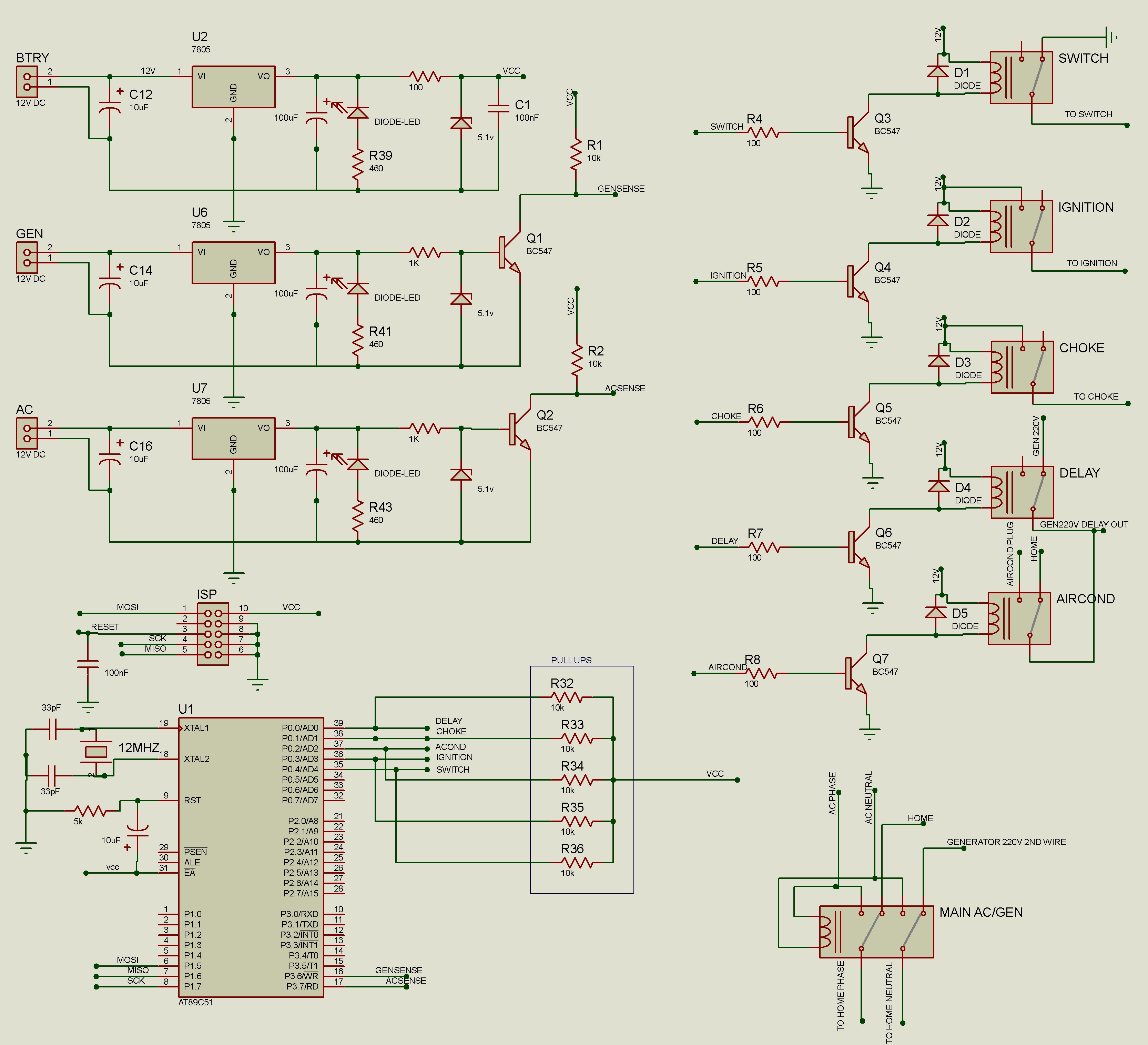
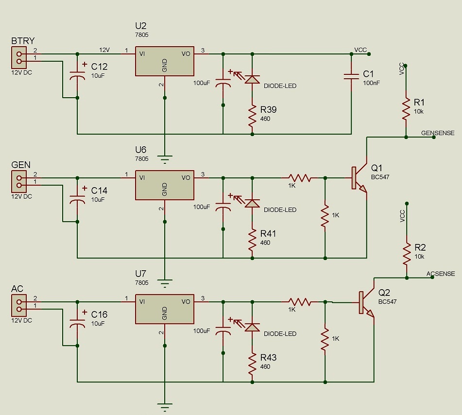
Hellow all i have designed generator automated transfer system. it is based on 89s51 which controls the operation. circuit uses LM7805 with 10uf16v before and 100uf16v after the regulator. i have also used 5.1v zener for protection against over voltage and 100pf for noise filtration. circuit senses 220v AC with the help of step down transformer and bridge rectifier. for the generator part it is available with 14v DC supply for secondary battery charging and i have used it to determine that the generator has started. my circuit works fine when it is connected to a test supply it also works fine when generator is turned off and battery power is used for test purpose. to cut short the elaboration part when circuit starts the generator and generator power led turns on but after some a while MCU seems to have stuck up as it turn of the switch relay causing the generator to shutoff. and when the generator is off it does not attempt to restart unless reset button is pressed. kindly help me with the issue as it is beyond my comprehension and i don't have scope to see what exactly is happening to the input voltage.
 

Post circuit. Use opto isolator for relay. Relay circuit should be isolated from MCU circuit. Relay switching is hanging the MCU as relay and MCU use the same power supply. Give details about relay used.
 
During starting (cranking time) battery voltage may go down too much and can be the cause of the trouble. So measure the battery voltage at that time using a voltmeter.
 
Post circuit. Use opto isolator for relay. Relay circuit should be isolated from MCU circuit. Relay switching is hanging the MCU as relay and MCU use the same power supply. Give details about relay used.

relay is not isolated by the optoisolator but i don't see a problem in relay being operated by transistor and 2ndly if the issue was due to relays then the result should have been same in test mode without generator. relays are simple 12V 5 pin relays

- - - Updated - - -

Post circuit. Use opto isolator for relay. Relay circuit should be isolated from MCU circuit. Relay switching is hanging the MCU as relay and MCU use the same power supply. Give details about relay used.

as far circuit it is quit a mess here is pcb Untitled.png with components detail if thats of any help or i can redraw the diagram
 

During starting (cranking time) battery voltage may go down too much and can be the cause of the trouble. So measure the battery voltage at that time using a voltmeter.
if battery voltage was the case it should have had trouble during ignition but if the generator does not start it keeps trying for the limited attempts and then waits up for the reset and if AC become available during starting process it stop the ignition attempts and waits till the light go again there is no issue with the main or ignition issue starts after the generator is functioning.

- - - Updated - - -

there may be a bug in the sampling code kindly identify if you see any or any improvements
Code:
#include<REG51.h>
sbit ac=P3^7;
sbit gen=P3^6;
sbit sw=P0^4;
sbit ign=P0^3;
sbit del=P0^0;
sbit chk=P0^1;
sbit rs=P1^2;
sbit ro=P1^3;
sbit ato=P1^0;
sbit man=P1^1;
sbit acrel=P0^2;

 
 void delay(unsigned int msec )
{
	int i ,j ;
	for(i=0;i<msec;i++)
	for(j=0; j<124; j++);
}
void main()
{
	int acstate=1;
	int genstate=0,ngs=0,nacs=0,i; //setting generator initial state to off ngs and nacs are new states of generator and ac
	int atos=1,mans=0;
  //int rss=0,ros=0,stt,mid,end; 
	ac=1;  gen=1;// setting input pins

	sw=0;ign=0;del=0;chk=0;acrel=0;man=1;ato=1;//setting auto and manual to input
	while(1)
	{
		
		if(atos==1&&mans==0)//when generator is on auto state
		{  
			while(1)
				{
				  if(!man)//if manual button is pushed it will check the state of the button for 2 second to make sure state remains same
					{
						 for(i=0;i<200;i++)
						 {
							 if(!man) 
								 {
							 delay(10);
							 continue;
									}
						else 
							break;	 
							}
					if(i>19)
						{mans=1;atos=0;break;}	 
					}
					
			 for(i=0;i<100;i++)//sampling the state of the AC and Generator for any change for 2 second to make sure state remains same
			  {
				ngs=!gen; nacs=!ac;//storing new generator and ac states
					delay(10);
				if(ngs==!gen&&nacs==!ac)//if previous state is same as before delay keep it
					continue;
				nacs=acstate;ngs=genstate;break;
			   }
					if(acstate!=nacs||genstate!=ngs)
					{ acstate=nacs;genstate=ngs;
						if(!(acstate)&&!(genstate))
						{int x=1;sw=0;chk=0;ign=0;delay(2000);
							 do
							 {
								  del=1;sw=1;chk=1;
								  delay(3000);
								 ign=1;
								 for(i=0;i<20;i++)
                  {
										if(!gen||!ac)
									{ign=0;chk=0;break;}
										delay(100);
								 }
								 chk=0;
								for(i=0;i<20;i++)
                  {
										if(!gen||!ac)
									{ign=0;break;}
										delay(100);
								 }								 
								ign=0;
								 delay(3000);
								 while(x>=4&&gen){del=0;sw=0;}
								 x++;
							 }while(gen&&ac);
             }
          
					else if(acstate&&genstate)
					 {
              del=1;
              delay(5000);
              sw=0;
							del=0;
					 }
					else if(acstate&&!(genstate))
					{sw=0; del=0;}
					else if(!acstate&&genstate)
					{
						delay(60000);
						del=0;
					}
				}
			}
		 }
		else if(mans && ! (atos))
			{
				while(1)
				{ if(!ato)
					{
						 for(i=0;i<20;i++)
						 {
							 if(!ato) 
								 {
							 delay(100);
							 continue;
									}
						else 
							break;	 
							}
					if(i>19)
						{mans=0;atos=1;}	
					}
					if(atos&&!ac)
					  { atos=1;mans=0;del=1; delay(5000);sw=0;del=0;acrel=0;
						break;
						}
				 else if(atos&&ac)
				 { atos=1;mans=0;acrel=0;break;}
					//rss=!rs;ros=!ro;
				 sw=1;
				/*if(!gen)
					 acrel=1;
					else
						acrel=0;
				if(rss&&!ros)
					{
						if(gen)
						{int x=1;
							do
							 {
								  del=1;sw=1;chk=1;ign=1;
								  delay(2500);
								  chk=0;
								  delay(1000);
								  ign=0;
								 delay(3000);
								  while(x>=4&&gen){del=0;sw=0;}
								 x++;
							 }while((gen));
							 delay(60000);
							 del=0;
							
             }
				
						 
					 }
				
			 else if(ros&&!rss&&!gen)
					{
						del=1;
						delay(10000);
						sw=0;
						del=0;
						acrel=0;
					}
				}
		}*/
	}
}
}
}
 
Last edited by a moderator:

If there is a bug, then your system should not work during test operation, which you already have done successfully.

but after some a while MCU seems to have stuck up as it turn of the switch relay causing the generator to shutoff.

Do you think that MCU stuck up at the moment when the generator magnetic contactor (between generator and load) try to operate ? If so, then EMI from the magnetic contactor may be the reason.

- - - Updated - - -

As you said about ignition, so your generator has spark plugs (not a diesel generator). EMI from spark plug cables also needed to be considered.
 
If there is a bug, then your system should not work during test operation, which you already have done successfully.
i changed the sampling time for ac and generator to 5 sec i.e. it reads the ac and generator state and then compares these values with current state after 5 seconds. for once i thought that my problem is resolved as generator worked until the light came back. but now once again it works for 4 5 minutes and then stops.
 

As you said about ignition, so your generator has spark plugs (not a diesel generator). EMI from spark plug cables also needed to be considered.
Yes the generator is not diesel its small 2.5KW stand by generator and how to rectify the EMI issue any suggestions ?????
 

1. Make sure generator earth/body is connected to circuit ground.
2. Provide RC low pass filter at the input of ADC.
3. Try to put the circuit board inside a metal box, and electrically connect the box with circuit ground.
 
You don't need 5.1V zener at the base of transistors because 0.7 to 0.8 V VBE is enough for transistor to get forward biased. Why 5.1V zener when you don't have to apply more than 0.8V to forward bias BC547 ?
 
Agree with post #12.
Besides supply current of AT89C51 can be maximum 20mA (from datasheet). So 100 ohms at output of U2 can not be accepted due to unacceptable IR drop (2V).
Also connecting a suitable resistor between base and emitter of Q1 and also Q2 will make them immune to weak signals.
See the suggested part of the circuit below.

 
You don't need 5.1V zener at the base of transistors because 0.7 to 0.8 V VBE is enough for transistor to get forward biased. Why 5.1V zener when you don't have to apply more than 0.8V to forward bias BC547 ?
the zener was from previous design where i used arduino uno as cpu but then i shifted to cheaper 89s51 and it can cause any issue as voltage is on .7 volts at VBE and transistor is working fine.
 

Agree with post #12.
Besides supply current of AT89C51 can be maximum 20mA (from datasheet). So 100 ohms at output of U2 can not be accepted due to unacceptable IR drop (2V).
Also connecting a suitable resistor between base and emitter of Q1 and also Q2 will make them immune to weak signals.
See the suggested part of the circuit below.
ic works fine in test circuits and when ic is connect VCC is 4.05 volts which is within working range.
 
Last edited by a moderator:

i wrote a new code very simple one i noticed that ic doesn't hang up but it some how shuts down the output ports without reason.
Code:
#include<REG51.h>
sbit ac=P3^7;
sbit gen=P3^6;
sbit sw=P0^4;
sbit ign=P0^3;
sbit del=P0^0;
int count=0;
 void acok();
 void noac();
 void delay(unsigned int msec )
{
	int i ,j ;
	for(i=0;i<msec;i++)
	for(j=0; j<124; j++);
}
void main()
{
	int acstate,i=0;
	ac=1;  gen=1;

	sw=0;ign=0;del=0;
	while(1)
	{
		if(!ac)//sampling when AC is ok
		{ 
			for(i=0;i<20;i++)
			  { delay(100);
					 if(!ac)
						  continue;
					 acstate=0;
				 }
				if(i==20)
					acstate=1;
			}
		if(ac)//sampling when there is no light
		{ 
			for(i=0;i<20;i++)
			  {  delay(100);
					 if(ac)
						  continue;
					 acstate=0;
				 }
				if(i==20)
					acstate=0;
			}	
		if(acstate)
					acok();
		else if(!acstate)
				  noac();
		 
	 }
 }
void acok()
  {
    if(!count)//enters this part only once when count is zero
		{  del=1; delay(5000);
			 sw=0;del=0;
		}
   count=1;
	}
 void noac()
	{
		if(count)// attemps to start only once when AC is off
		{
			sw=0;chk=0;ign=0;delay(2000);
			del=1;sw=1;ign=1;
				delay(8000);//8 second for one time ignition
			ign=0;
			delay(60000);
			count=0;	del=0;				 
		}					 
	 }
in this code it doesn't even detect weather generator is on or not it only attempts once. i made little change in the circuit so when generator start it sinks the ignition transistor current and stops ignition total hardware no software for generator part. when i executed the code generator start for a while and turned off again and when i plugged in ac it went to first function engaged delay etc. upon removing the ac it restarted the generator but again turned it off after a while. i don't get it that why MCU automatically writes 0 to all output ports as input port is high. or may b it breaks through the while loop some how ???
 
Last edited:

ic works fine in test circuits and when ic is connect VCC is 4.05 volts which is within working range.

Based on datasheet specified conditions, minimum recommended Vcc for AT89S51 is 4.0V . Your supply voltage (4.05v) is critically valid but may not suitable for noisy conditions. So it is better to eliminate the 100 ohms resistor with associated zener diode.
Also see point 1 and 3 of post #10.
Yes, according to post #16, searching the root cause by changing the software is a good way.
 
thank you all i got ride of 100 ohms resistor and put in 3 leds for the indication that MCU is in which part of the code i also added 47uF Capacitor before LM7805 and the circuit has started working. it worked fine today now i will burn the old firmware to see weather the System is working fine or not thanks again to every one
 

Please explain the working of ATS is detail. I will write a code in mikroC.
 
Status
Not open for further replies.

Similar threads

Part and Inventory Search

Welcome to EDABoard.com

Sponsor

Back
Top