JHarmon
Newbie level 3
(Please excuse any stupid questions, I'm new to this)
I'm trying to generate a 5V clock signal to be used with this 74LS00 series binary counter:
**broken link removed**
I need a 4 MHz signal, but I'm really struggling to get any clock designs to work. What kind of circuit will be the easiest way to accomplish this?
Right now I'm trying to use a quartz oscillator like this one:
**broken link removed**
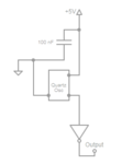
Current Circuit (Not very good with this diagramming program...), does anyone see a problem with that?

I'm using a 74LS04 inverter there to buffer the signal up to 5V.
Any suggestions? Once again, I'm really struggling.
Edit: The top left corner of the oscillator in the diagram is the squared off corner (Pin #1)
I'm trying to generate a 5V clock signal to be used with this 74LS00 series binary counter:
**broken link removed**
I need a 4 MHz signal, but I'm really struggling to get any clock designs to work. What kind of circuit will be the easiest way to accomplish this?
Right now I'm trying to use a quartz oscillator like this one:
**broken link removed**
Current Circuit (Not very good with this diagramming program...), does anyone see a problem with that?

I'm using a 74LS04 inverter there to buffer the signal up to 5V.
Any suggestions? Once again, I'm really struggling.
Edit: The top left corner of the oscillator in the diagram is the squared off corner (Pin #1)