Continue to Site

Welcome to EDAboard.com

Welcome to our site! EDAboard.com is an international Electronics Discussion Forum focused on EDA software, circuits, schematics, books, theory, papers, asic, pld, 8051, DSP, Network, RF, Analog Design, PCB, Service Manuals... and a whole lot more! To participate you need to register. Registration is free. Click here to register now.

generating 2 pulses using vhdl code

Status
Not open for further replies.

preethi19

Full Member level 5
Joined
Jun 30, 2014
Messages
273
Helped
0
Reputation
0
Reaction score
1
Trophy points
16
Activity points
3,474
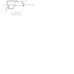
Hi i need to generate 2 pulses. I need to clock the pulses in a way that when the signal "level" is asserted pulse 1which is normally low becomes high for 2 clock cycles while pulse 2 which is normally high becomes low for 1 clock cycle. Can anyone please help me with a sample vhdl code from where i can build it myself. Thanks a lot!!!


Code Verilog - [expand]
1
2
3
4
5
6
7
8
always@(posedge(clk))
begin
if(level == 1'b1)
  pulse1_1 <= 1'b1;
pulse1_2 <= pulse1;
end
 
assign pulse1 = pulse1_1 or pulse1_2;


This is for pulse1. You can think on the same lines for pulse2...
 
Last edited by a moderator:
always@(posedge(clk))
begin
if(level == 1'b1)
pulse1_1 <= 1'b1;
pulse1_2 <= pulse1;
end

assign pulse1 = pulse1_1 or pulse1_2;

This is for pulse1. You can think on the same lines for pulse2...
Depending on the routing this could result in a glitch in the middle of the pulse1 output. Also this circuit would not generate a pulse as there is no way to reset pulse1_1 back to 0.

The following pulse generator should do what you want for pulse1, as long as level is synchronous to clk and persists for at least 3 clock cycles.

Code Verilog - [expand]
1
2
3
4
always @ (posedge clk) begin
  pipe[1:0] <= {pipe[0], level}; // two clock delay
  pulse1 <= level & ~pipe[1];  // detect leading edge of level and generate pulse for two clock cycles
end

 
  • Like
Reactions: wtr

    wtr

    Points: 2
    Helpful Answer Positive Rating
Thanks for the reply!!! I have the requirement to design this two pulses generator using d flip flops and logic gates. I managed to design the circuit with d flip flop, an OR gate and a NAND gate to satisfy the conditions i mentioned earlier for the 2 pulses. D and Q are ORed to get pulse 1 and then pulse 1 and Q are NAND to get pulse 2... This is the logic... Can anyone give me an vhdl sample code for this.. Would be really great if anyone could help!!! :)
 

Unless you give us a logic diagram we cannot tell you whether your circuit is correct. Only when your circuit is correct does it make sense to help you with the code.
 

Expanding on what was stated above

Code Verilog - [expand]
1
2
3
4
always @ (posedge clk) begin
  pipe[1:0] <= {pipe[0], level}; // two clock delay
  pulse1 <= level & ~pipe[1];  // detect leading edge of level and generate pulse for two clock cycles
end


This can be translated into vhdl,
Where posedge clk = rising_edge
Where ~ = not
Where & = AND
Therefore see the following translation

Code VHDL - [expand]
1
2
3
4
if rising_edge(clk) then
  pipe <= pipe(0) & level;
  pulse1 <= level AND not pipe(1); -- responds on edge
end if;


I normally work out the falling and rising edge using a registered process, HOWEVER this adds 1 clk delay

Code VHDL - [expand]
1
2
3
4
5
6
7
8
process(clk)
begin
  if rising_edge(clk)
    level_reg <= level;
  end if;
end process;
level_re <= level and not level_reg;
level_fe <= not level and level_reg;


Tweak the above for pulse2
 

hi i have attached an image for ur verification... The circuit i tried to meet the conditions for generating those 2 pulses... I am totally new to vhdl so i am finding it little hard. I am able to manage the logic define input outputs but the problem for me always is defining the clock. i dont know how to set clk in a way that for 2 periods of clock pulse 1 is high and then reset is set and it goes low... while after 1 period of clock for the 2nd clock period the pulse 2 which is normally high should go low just for that period and then reset is set again for that too to bring it back to high... Can anyone plssss help me setting up the clock timing in code... Thank you!!!!

- - - Updated - - -

Its like the exact problem is i don't understand if i should first generate a clock and then mention during its rising edge or should i directly in my code just define clk as input and proceed the logic with rising edge. Also i am confused with how to add the period cycles for the clock say for first rising edge i give the logic for pulse 1 to be set high... how can i proceed with the logic to make pulse 1 high for the 2 nd clock cycle too??? like by now you must know i am totally confused with using clock in code though i understand the logic. Can anyone explain simple terms about the above problem and in general abt clck... pls becoz i really need to learn clock signal for my other programs too...
 

Attachments

  • pulse generator.png
    pulse generator.png
    39.2 KB · Views: 112

Your timing diagram is wrong. The pulse1 will go high after the delay of the OR gate and stay high as long as level is a logic 1.

Also the feed through of the level will not guarantee a two clock cycle pulse width of the pulse1.

I previously gave you a Verilog example that produces a pulse exactly 2 clocks wide (based on the rising edge of the clock) and only does it when the leading rising edge of level occurs.

I also have no clue what you mean by how to generate the clock. Are you referring to how to generate a clock in a testbench?
 

What is happening is as follows


clk | level | Pipe(0) | Pipe(1) | Pulse1
0 | 0 | 0 | 0 |
1 | 0 | 0 | 0 |
0 | 0 | 0 | 0 |
1 | 1 | 0 | 0 | 1
0 | 1 | 0 | 0 | 1
1 | 1 | 1 | 0 | 1
0 | 1 | 1 | 0 | 1
1 | 1 | 1 | 1 |
0 | 1 | 1 | 1 |
1 | 1 | 1 | 1 |
0 | 1 | 1 | 1 |
1 | 1 | 1 | 1 |
0 | 1 | 1 | 1 |
1 | 1 | 1 | 1 |
0 | 1 | 1 | 1 |
1 | 1 | 1 | 1 |


Where pulse1 is two clocks cycles
 

Clock is an input to your circuit. You have to use it to generate pulse1 and pulse2 like in rising_edge(clk). You can assume a clock of the form which you showed in your diagram.
 

Status
Not open for further replies.

Part and Inventory Search

Welcome to EDABoard.com

Sponsor

Back
Top