Continue to Site

Welcome to EDAboard.com

Welcome to our site! EDAboard.com is an international Electronics Discussion Forum focused on EDA software, circuits, schematics, books, theory, papers, asic, pld, 8051, DSP, Network, RF, Analog Design, PCB, Service Manuals... and a whole lot more! To participate you need to register. Registration is free. Click here to register now.

generate an alternate voltage to low power

Status
Not open for further replies.

erchiu

Member level 5
Joined
Apr 7, 2012
Messages
93
Helped
2
Reputation
4
Reaction score
1
Trophy points
1,288
Location
Rome - Italy
Activity points
2,082
hi at all,
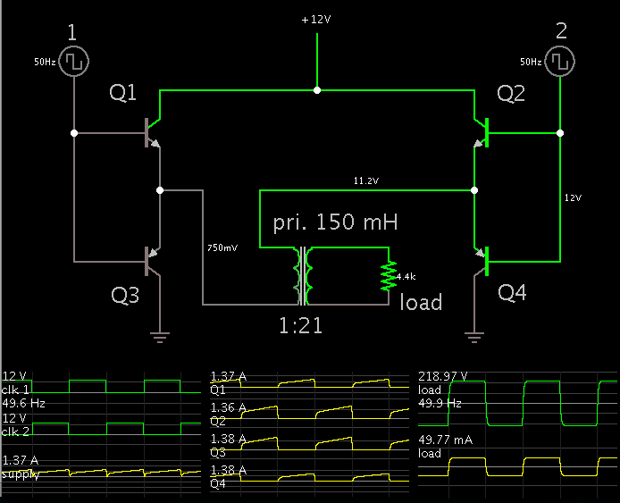
i am realizing an electric circuit where there are two components that need of 220 vac supply but i have only an 12v dc supply provided from an battery
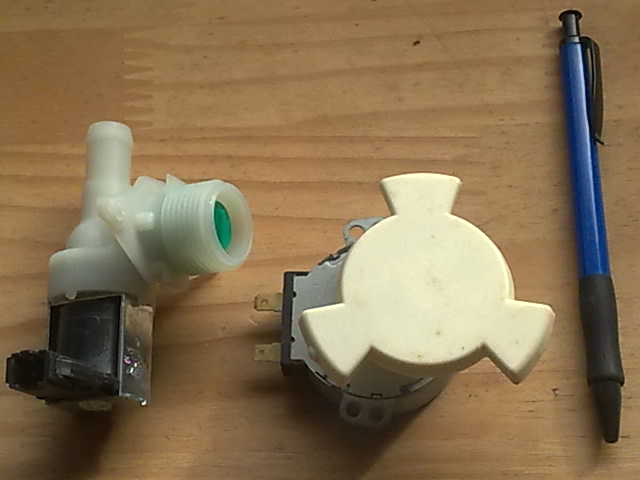
these components are one electric valve (7w/220vac) and little motor (4w/220vac) and must operate for several seconds.
how i can do for use this components starting from an dc voltage?
if it's possible,i would like avoid to use an inverter for this purpose but insert an little section into my circuit and generate this AC voltage
thank you for the help
erchiu
 

12VDC to 220VAC is done with an inverter. You can build one for a lot of money and it might not work or you can buy a little 75W inverter for the same cost as two coffees in a restaurant.
 

thank you for the answer.
i would like avoid to insert another additional circuit.
i was hoping that adding some components was possible steer these components.
i not need of a pure wave form, but it is important that these components work good.
the rest of the circuit operate with low voltage, electric valve and the little motor only need of this AC voltage.
bye erchiu
 

The simplest technique is to use a full H-bridge to chop the 12V into square waves. Send the square waves through a step-up transformer.

The load draws about 11W.

The transformer does not necessarily have to be a 20 or 21X step up. It can be less, but then it will be uncertain whether it will turn the motors.


The simplest inverter for this sort of use is a 12 -0 -12 V to 230 V mains transformer, take the centre tap to +12V, the 12V ends take to - 12V via two power transistors, drive these transistors with out of phase 50 HZ squarewaves. Put a snubber network across the 12 v ends to remove overshoots due to leakage inductance (.1 MF + 10 ohms).
Frank
 

thank you for this help. I am not very strong in electronic field. You could post the circuit. thank you still erchiu
 

i am watching the circuit above, but i have some questions to do.
1) the point 1 and 2 are connected to an generator of square type wave astable multivibrator ? if it ok, i can use an ne555 configurated in this mode?
2) the transistor are 2 pnp and 2 npn. what features must have them?
3) the transformer must have the primary winding of 150 mH, what features must have the secondary winding?
i measured the winding of the components that i must drive with this circuit, electric valve 3.35 kohm and the motor 11,85 kohm

sorry for the trivial questions for you but I would help you understand and solve the problem.
thanks to everyone for the help
greetings erchiu
 

The transformer is a 12 to 232 V mains transformer! The transistors must be rated for at least 24 v at 5A. You can use a NE555, but you will need an extra low power transistor to give you an inverted wave form. When point 1 goes +ve , point 2 must go -ve. i would still put a snubber across the primary of the transformer.
Frank
 

thank you frank,
you are helping me a lot.
for the transformer i can use an normal transformer 12v/232v 20/30 va is good?
for the transistor can i use the tip122 and tip127 are 5A and 100v it's ok?
but i not understand as generate the wave form to send to point 1 and 2.
you could explain it in a more simple or could post the circuit.
thank you for your help
greetings erchiu
 

for the transformer i can use an normal transformer 12v/232v 20/30 va is good?

It is not likely you can take a step-down transformer, and turn it around to become a step-up.

The 230V winding is made to show a high impedance to the electric company. (The electric company is very low ohms.) Your situation is the opposite. You have a high impedance load. Therefore you want the 230 V winding to have a comparatively low impedance.

Only if you are lucky will you find an everyday transformer with specs that work for your purposes. I believe it would be larger than you need (say, 2 inches on a side). It would be rated for greater watts than you need.

There is an alternate approach we have not brought up. It may be suitable because your current load is small. First use a boost converter to step up 12 VDC to 230 VDC. Since the operating frequency can be high, the coil can be very small and inexpensive.

Then chop the 230 VDC at 50 Hz through an H-bridge (4 transistors/mosfets). This gives you 230 VAC.
 

Sorry Bradtherad, the flux in a transformer does not know in which winding the current is flowing. The losses in mains transformers will be roughly equalised between the primary and the secondary so there will be only a few percentage difference in regulation, the main difference will be in the change from sine wave to square wave, which will give a lot of overshoots on the output square wave - load it with a snubber to cure.
Frank
 

A hobby website in Japan http://www.piclist.com/images/www/hobby_elec/e_menu.htm has a simple 110W squarewave inverter project. The mains electricity in Japan is 100VAC.
The output voltage of the inverter is shown to have fairly poor voltage regulation since it is 10% too high with no load and drops to 8% too low with a 110W load.
The 12V battery must be pretty big and heavy to provide 10A continuously for any reasonable length of time.
 

Attachments

  • 110W squarewave inverter.png
    110W squarewave inverter.png
    159.9 KB · Views: 104

Sorry Bradtherad, the flux in a transformer does not know in which winding the current is flowing...

Right, since it converts 12W in one direction, then it should be able to convert 12W in the other direction. That is, theoretically, and if nothing else interferes.

Here is how I see it:

4982686700_1391176685.gif


In the first diagram...
The transformer converts our specified 12W. Its primary side shows an impedance of 4400 ohms to the electric company (at 230 VAC).

In the second diagram...
The transformer delivers 230 VAC through 2 x 4400 ohms total impedance. The load does not get the entire 230 VAC. Rather it gets half of that.

I think the transformer will need a much higher power rating, in order for the primary to have low enough impedance for the load to get sufficient voltage across it.

Of course it is essential that we factor in DC resistance of the winding. I just measured several small wall wart adapters, using my ohmmeter. The primaries range from 100 to 500 ohms. This by itself will reduce voltage on a 4400-ohm load hooked up in series.

Transformer theory is complicated, and I realize I could be wrong. I once tried to make a homebrew inverter, starting with a big step-down transformer, 4 inches on each side. I could barely get a 7W bulb to light. I believe it was because the transformer primary had high internal impedance.
 

hello to all.
I read the article posted by the inverter on the Japanese site AudioGuru and I have seen that can 'be adapted without major changes only by replacing the transformer to the voltage of 220v.
the circuit it seems quite easy to implement and does not require many components.
the transformer should be small since it needs be only a few watts (max 7 for the solenoid).
I think I do it this way or at least I try.
Thanks to all for the help you have given me so far
greetings erchiu
 

Status
Not open for further replies.

Part and Inventory Search

Welcome to EDABoard.com

Sponsor

Back
Top