Continue to Site
Follow along with the video below to see how to install our site as a web app on your home screen.
Note: This feature may not be available in some browsers.
Hi,
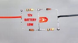
see the picture below. Here the voltage on the cathode will drop faster than on the anode side. The voltage drop at D1 is constant (until undercutting the zener voltage of 6.2 V), thus the voltage across R1 (Cathode) will decreases when V(PLUS) decreases. The LED will start to light up when the required forward voltage across the LED will drop. This means that the voltage at the cathode and consequently the PLUS voltage has to drop by about the forward voltage of the LED to light up, and to indicate a voltage drop. By choosing a specific LED color, you can select a rough indication threshold voltage [1].

 byjus.com

Can you run my linked simulation and answer this yourself with Ohm's Law?hello
how led is on can you explain how resistance is truning on led on battery is low
Zeners draw all the resistor current until the LED turns on.Can you run my linked simulation and answer this yourself with Ohm's Law?
Look at traces with mouse pointer.
If you don't understand Ohm's Law , how can I explain.