Continue to Site

Welcome to EDAboard.com

Welcome to our site! EDAboard.com is an international Electronics Discussion Forum focused on EDA software, circuits, schematics, books, theory, papers, asic, pld, 8051, DSP, Network, RF, Analog Design, PCB, Service Manuals... and a whole lot more! To participate you need to register. Registration is free. Click here to register now.

generate a 8 psk signal matlab code

Status
Not open for further replies.

karlakos

Newbie level 1
Joined
Feb 26, 2009
Messages
1
Helped
0
Reputation
0
Reaction score
0
Trophy points
1,281
Activity points
1,294
psk modulation

Hallo to everybody!

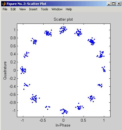
I am building in matlab an 8ary-PSK modulator with the presence also of awgn noise.. Does somebody have any code to implement this in matlab? Because i have some problems..

Thanks in advance!!
 

psk matlab

Hi dear see this (my program)

clc;
clear all;
disp('M-Array PSK Modulation')
%create a random digital message
M=input ('M= '); %alphabet size
x=randint(input('Number of binary bit stream = '),1,M);

nsample=40; %oversampling rate.
%%

%%
%use M-PSK modulation to produce y
y=modulate(modem.pskmod(M),x);
%%
%follow with rectangular pulse shaping.
ypulse=rectpulse(y,nsample);
stem(y(1:10),'filled'),grid;
%%
%%transmit signal through an AWGN Channel
ynoisy=awgn(ypulse,input('SNR in dB = '),'measured');
%%
%Create scattet plot from noisy data
scatterplot(ynoisy),grid;
%%
%Downsample at the reciever.
ydownsample=intdump(ynoisy,nsample);
%%
%Demodulate ynoisy to recover the message.
z=demodulate(modem.pskdemod(M),ydownsample);
figure;
subplot(2,1,1);
stem(x(1:10),'filled'),grid;
subplot(2,1,2);
stem(z(1:10),'filled'),grid;
%%
%Check symbole erroe rate.
[num ty]=symerr(x,z)

enjoy
 
psk matlab code

Aya2002 said:
Hi dear see this (my program)

clc;
clear all;
disp('M-Array PSK Modulation')
%create a random digital message
M=input ('M= '); %alphabet size
x=randint(input('Number of binary bit stream = '),1,M);

nsample=40; %oversampling rate.
%%

%%
%use M-PSK modulation to produce y
y=modulate(modem.pskmod(M),x);
%%
%follow with rectangular pulse shaping.
ypulse=rectpulse(y,nsample);
stem(y(1:10),'filled'),grid;
%%
%%transmit signal through an AWGN Channel
ynoisy=awgn(ypulse,input('SNR in dB = '),'measured');
%%
%Create scattet plot from noisy data
scatterplot(ynoisy),grid;
%%
%Downsample at the reciever.
ydownsample=intdump(ynoisy,nsample);
%%
%Demodulate ynoisy to recover the message.
z=demodulate(modem.pskdemod(M),ydownsample);
figure;
subplot(2,1,1);
stem(x(1:10),'filled'),grid;
subplot(2,1,2);
stem(z(1:10),'filled'),grid;
%%
%Check symbole erroe rate.
[num ty]=symerr(x,z)

enjoy

I face the difficulty to run your program. Could you please help to look at it?
There is an error message with undefine (modem.pskmod(M),x);
 

psk matlab program

Hi Dear,
which version of matlab u r using, it must be 2008.
 

psk modulation in matlab

hi
i face the same problem in MATLAB 7.0
why the most of programs dont run successfully!!
thanks .
arwa
 

psk modulation matlab

Hi aarr,

this program written in matlab 2008, u need to run it on this version.

Regards
 

matlab program for digital modulation techniques

Do not use the modem object. See which command is being used in M7 for modulattion. Matlab has a habit of changing the command from modulate, pskmod, modem....

So find that command and use it instead
 

matlab bpsk

Hi friend: see this for matlab below 2008 version

Simple Digital Modulation Example

This example illustrates the basic format of the baseband modulation and
demodulation commands, dmodce and ddemodce. Although the example uses the PSK method, most elements of this example apply to digital modulation techniques other than PSK.

The example generates a random digital signal, modulates it, and adds noise.
Then it creates a scatter plot, demodulates the noisy signal, and computes the
symbol error rate. The ddemodce function demodulates the analog signal y and
then demaps to produce the digital signal z.

Notice that the scatter plot does not look exactly like a signal constellation.
Whereas the signal constellation would have 16 precisely located points, the
noise causes the scatter plot to have a small cluster of points approximately
where each constellation point would be. However, the noise is sufficiently
small that the signal can be recovered perfectly. Below are the code and the scatter plot.

M = 16; % Use 16-ary modulation.
Fd = 1; % Assume the original message is sampled
% at a rate of 1 sample per second.
Fs = 3; % The modulated signal will be sampled
% at a rate of 3 samples per second.
x = randint(100,1,M); % Random digital message
% Use M-ary PSK modulation to produce y.
y = dmodce(x,Fd,Fs,'psk',M);
% Add some Gaussian noise.
ynoisy = y + .04*randn(300,1) + .04*j*randn(300,1);
% Create scatter plot from noisy data.
scatterplot(ynoisy,1,0,'b.');
% Demodulate y to recover the message.
z = ddemodce(ynoisy,Fd,Fs,'psk',M);
s = symerr(x,z) % Check symbol error rate.
s =
0

93_1236684279.jpg


Customizing the Modulation Process
the modulation and demodulation processes each consist of two steps. You can tell the toolbox functions to carry out only selected steps in the processes. For example, this might be useful if you want to use standard mapping and demapping
techniques along with unusual or proprietary modulation and demodulation techniques.

Mapping Without Modulating and Demapping Without Demodulating
To map the digital signal to an analog signal without modulating the analog
signal, use the modmap function instead of the dmodce function. To demap the
analog signal to a digital signal without demodulating the analog signal, use
the demodmap function instead of the ddemodce function.

To alter the basic example so that it does not modulate or demodulate the
analog signals at all, replace the “old commands” listed in the first column of
the table below with the “new commands” listed in the second column.


Modulating Without Mapping and Demodulating Without Demapping

To carry out the analog modulation step on a signal that has already been
mapped from a digital signal to an analog signal, use the dmodce function with
the extra word /nomap appended to the method string. To carry out the analog
demodulation step but avoid demapping the resulting signal to a digital signal,
use the ddemodce function with the extra word /nomap appended to the method
string.

If you substituted your own mapping and demapping steps into the basic
example then it would look something like the code below. The lines in the
second grouping differ from the original example.

M = 16; % Use 16-ary modulation.
Fd = 1; % Assume the original message is sampled
% at a rate of 1 sample per second.
Fs = 3; % The modulated signal will be sampled
% at a rate of 3 samples per second.
x = randint(100,1,M); % Random digital message
% Important changes are below.
mapx = mymappingfunction(x); % Use your own function here.
y = dmodce(mapx,Fd,Fs,'psk/nomap',M); % Modulate without mapping.
% Demodulate y without demapping.
demody = ddemodce(y,Fd,Fs,'psk/nomap',M);
% Now demap.
z = mydemappingfunction(demody); % Use your own function here.

Other Options in Digital Modulation
The table below lists a few ways in which you might vary the example in
“Simple Digital Modulation Example” on page 2-77 in order to perform the
modulation and demodulation slightly differently. See the reference pages for
full details about options.


Good luck
 
Re: psk matlab

Hi Aya,
After the psk modulation you have used rectangular pulse so that the scatterplot is look like nice. But when I am using root raised cosine pulse, it is not like this... see how I implemented

rc=rcosine(1,nsample,'sqrt',0.5);
x=rcosflt(y,1,nsample,'filter',rc);
scatterplot(x),grid;


could you please help me about that?
 

Status
Not open for further replies.

Similar threads

Part and Inventory Search

Welcome to EDABoard.com

Sponsor

Back
Top