Continue to Site

Welcome to EDAboard.com

Welcome to our site! EDAboard.com is an international Electronics Discussion Forum focused on EDA software, circuits, schematics, books, theory, papers, asic, pld, 8051, DSP, Network, RF, Analog Design, PCB, Service Manuals... and a whole lot more! To participate you need to register. Registration is free. Click here to register now.

[SOLVED] gate Leakage current and pull up resistor

Status
Not open for further replies.

Bou

Full Member level 3
Joined
Mar 6, 2013
Messages
159
Helped
0
Reputation
0
Reaction score
0
Trophy points
16
Activity points
0
Hello,

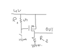
I designed the schematic (picture attached) , and my question is about the pull up resistor R1 when I choose a value of 4MOhms I notice that there is a difference of voltage of 1 V between the supply (4V) and the gate of the PMOS and this difference is reduced when I decrease the value of R1 (0.5 V for 1.5 Mohms), is this due to the leakage current of the gate?? is that normal? I think that the gate current is very low and I should have the same voltage (4 V)at the gate!!!!!
schema.png
 

Are you taking into account the current flowing in to the volt meter itself?

It is unusual to configure a MOSFET circuit like that, the resistor is a 'pull down' and the switch connects the gate to ground to turn the MOSFET on. Is that what you intended?
There will be some leakage into the gate as well, it will be very small but 4M limits the possible current to only 0.1uA even when the switch is closed.

Brian.
 

The mosfet is initially OFF and when the switch is closed it turns ON

Whith a high value of resistance even a smal walue of 0.1 uA can cause a drop voltage of R1*0.1 uA=0.5 V

whith a small value of R1, let 's take 10 K, I think that will work very well, But I m obliged to use a high value of some Mohms.

is that difference is normal in this case?
 

Hi,

just use the 4M resistor (without mosfet) and connect it to your 4V. Now use your DMM and measure the voltage on both ends of the resistor.

One value should be the 4V. But what is the other?

Klaus
 

Hi,

just use the 4M resistor (without mosfet) and connect it to your 4V. Now use your DMM and measure the voltage on both ends of the resistor.

One value should be the 4V. But what is the other?

Klaus


Hi,

I do as you demand,

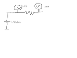
It's strange !!!!!! picture attached

why there is trhis difference Now Im confused
I get the same result for my mosfet schematic using DMM and oscilloscope
schema.png
 
Last edited:

The meter itself is drawing current and pulling the voltage down. Think of it like a potential divider with the physical resistor at the top and the internal resistance of the meter at the bottom. What you are seeing is the voltage at the middle. Most DMM have around 10M input resistance and your oscilloscope input attenuator is probably around the same so you create a potential divider with 4M at the top and 10M at the bottom.

Brian.


Yaah. You are right

I get it, I thought that the DMM had a greater impedance!!!!
 

Status
Not open for further replies.

Similar threads

Part and Inventory Search

Welcome to EDABoard.com

Sponsor

Back
Top