ammar_kurd
Junior Member level 3
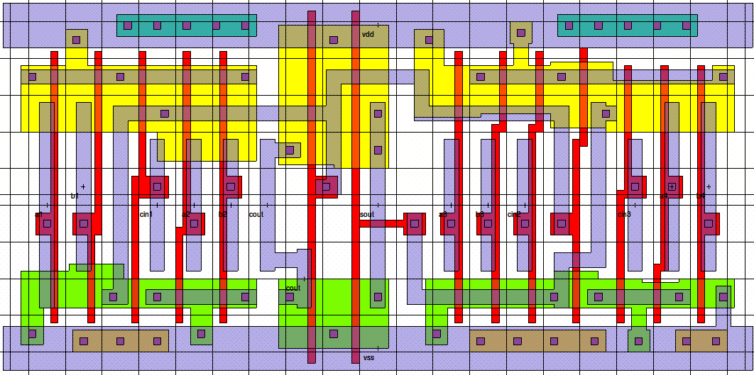
Hello everyone , I would like to use a full adder standard cell in my project I am using Magic layout tool, I found one in the ssxlib library in vlsithechnology.org, the problem is it's not documented, it seems like it is a four bit full, the ports labels available are,
(a1 b1 cin1), (a2, b2, cin2), (a3, b3, cin3), (a4, b4), (sout, cout)
there is no cin4, and shouldn't be there sout1, sout2,...
aslo cout1, cout2,...
Please help me guys, I am new to this.
cna you tell me how to use this, or any other advice will be appreciated.
(a1 b1 cin1), (a2, b2, cin2), (a3, b3, cin3), (a4, b4), (sout, cout)
there is no cin4, and shouldn't be there sout1, sout2,...
aslo cout1, cout2,...
Please help me guys, I am new to this.
cna you tell me how to use this, or any other advice will be appreciated.