Continue to Site

Welcome to EDAboard.com

Welcome to our site! EDAboard.com is an international Electronics Discussion Forum focused on EDA software, circuits, schematics, books, theory, papers, asic, pld, 8051, DSP, Network, RF, Analog Design, PCB, Service Manuals... and a whole lot more! To participate you need to register. Registration is free. Click here to register now.

FRG-7 BFO convert to ceramic resonator

Status
Not open for further replies.

neazoi

Advanced Member level 6
Joined
Jan 5, 2008
Messages
4,123
Helped
13
Reputation
26
Reaction score
15
Trophy points
1,318
Location
Greece
Activity points
36,955
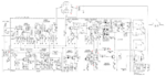
Hi I wonder if I can convert the BFO (Q408) of this receiver to use a ceramic resonator without too much changes in the BFO circuit, so as not to have to alter many things onto the PCB.

Can I somehow connect a ceramic resonator there and/or maybe remove 1-2 components and convert it into a more stable one?
How about replacing this R439 with a ceramic resonator?

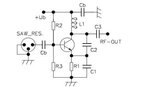
I see some similarities with the attached colpitts oscillator with common base.
 

Attachments

  • frg-9_mods1.PNG
    frg-9_mods1.PNG
    501.8 KB · Views: 179
  • Colpitts oscillator with common base.jpg
    Colpitts oscillator with common base.jpg
    13.2 KB · Views: 157
Last edited:

It might work but I doubt you would see any improvement. The SAW circuit is usually used at much higher frequencies (> 300MHz) so it may need some adapting to go down to 455KHz. You would also have problems shifting to the opposite sideband . You wouldn't want a 455KHz resonator, you would need two, one about 453.5KHz and one at 456.5KHz. Switching capaciance across it as used in the original wouldn't allow for shifting up and down but you might be able to start at 456.5KHz and 'pull' it 3KHz down with a capacitor.

Brian.
 

    neazoi

    Points: 2
    Helpful Answer Positive Rating
It might work but I doubt you would see any improvement. The SAW circuit is usually used at much higher frequencies (> 300MHz) so it may need some adapting to go down to 455KHz. You would also have problems shifting to the opposite sideband . You wouldn't want a 455KHz resonator, you would need two, one about 453.5KHz and one at 456.5KHz. Switching capaciance across it as used in the original wouldn't allow for shifting up and down but you might be able to start at 456.5KHz and 'pull' it 3KHz down with a capacitor.

Brian.
I rebuilt the circuit on a breadboard and I connected a 455KHz ceramic resonator from the drain to the ground. I am not sure if it improved stability, but for sure it did not made this worst. But I am using another coil than that of the frg-7.
I noticed a decrease in frequency of 50KHz with the ceramic resonator to ground. When I added a series capacitor to the resonator to ground, the shift was less.
Also with just the ceramig resonator and no extra series capacitor I could still use the top variable capacitor to shift the frequency on USB.

But I am not sure in which places to try the resonator. Is what i did on the drain correct? What other places?
 

Status
Not open for further replies.

Part and Inventory Search

Welcome to EDABoard.com

Sponsor

Back
Top