Prabhakarankft
Member level 3
- Joined
- Jun 22, 2019
- Messages
- 54
- Helped
- 0
- Reputation
- 0
- Reaction score
- 4
- Trophy points
- 8
- Location
- Chennai, India
- Activity points
- 623
Hello Everyone.
Greetings. Recently I have developed a project with a lot of 74HC595D SMD IC.
A brief explanation about my project:
The actual purpose of my project is to control nearly 900-2000 solenoids( about 15V and 25mA each solenoid).
We have three separate boards to handle the user input and controls the solenoids.
MotherBoard--> Slave Board--> Driver Cards.
The real problem exists in the driver card. Distribution boards are sending the data to driver cards. Since my application is to control a large number of solenoids each driver's card is daisy-chained in connection.
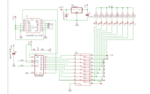
The circuit inside the driver cards is so easy. We have a 74HC595 IC(P.No: 74HC595D,118 ) and ULN2803 (P.No: TBD62083AFWG). I am using 7805(P.no: L78M05CDT-TR, STM ) to give voltage to 74HC595 IC.
Operation wise everything is working fine. But many times 74HC595 IC is getting failure after some days or months sometimes. We will insert the driver cards directly to the solenoid box Like RAM ports in computers(Such a way solenoid boxes are designed- Each box contains 8 solenoids)
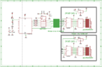
Distribution boards are having dedicated FRC headers with a latch to connect Driver cards. We using Flat Ribbon cable(14 way - Neltron brand 28AWG) to connect the distribution board and driver cards. 1 Connector will handle 16/26 number of driver cards. All driver cards are daisy-chained.
Clock pin, Latch Pin, and OE pins of 74HC595 ICs are connected parallelly and it is connected to 74LS244N( HEX Buffer) for isolation purposes. The data input for the driver card is directly coming from the MCU which is in the Distribution board. We found many failures in the 74HC595 IC and some times one/two channels in the hex buffer.
If We change 595 IC in the defected driver card, it is working properly. We need to know the cause of this problem. Kindly help me out.
Sorry for bbbbbbiiiigggggg storyyyyyy..
Greetings. Recently I have developed a project with a lot of 74HC595D SMD IC.
A brief explanation about my project:
The actual purpose of my project is to control nearly 900-2000 solenoids( about 15V and 25mA each solenoid).
We have three separate boards to handle the user input and controls the solenoids.
MotherBoard--> Slave Board--> Driver Cards.
The real problem exists in the driver card. Distribution boards are sending the data to driver cards. Since my application is to control a large number of solenoids each driver's card is daisy-chained in connection.
The circuit inside the driver cards is so easy. We have a 74HC595 IC(P.No: 74HC595D,118 ) and ULN2803 (P.No: TBD62083AFWG). I am using 7805(P.no: L78M05CDT-TR, STM ) to give voltage to 74HC595 IC.
Operation wise everything is working fine. But many times 74HC595 IC is getting failure after some days or months sometimes. We will insert the driver cards directly to the solenoid box Like RAM ports in computers(Such a way solenoid boxes are designed- Each box contains 8 solenoids)
Distribution boards are having dedicated FRC headers with a latch to connect Driver cards. We using Flat Ribbon cable(14 way - Neltron brand 28AWG) to connect the distribution board and driver cards. 1 Connector will handle 16/26 number of driver cards. All driver cards are daisy-chained.
Clock pin, Latch Pin, and OE pins of 74HC595 ICs are connected parallelly and it is connected to 74LS244N( HEX Buffer) for isolation purposes. The data input for the driver card is directly coming from the MCU which is in the Distribution board. We found many failures in the 74HC595 IC and some times one/two channels in the hex buffer.
If We change 595 IC in the defected driver card, it is working properly. We need to know the cause of this problem. Kindly help me out.
Sorry for bbbbbbiiiigggggg storyyyyyy..