pradhan.rachit
Full Member level 3
Hello Experts!
I am in the process of designing a frequency division multiplexing trainer kit for laboratory demonstration purposes.
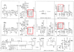
The circuit has to be designed on the lines of an existing design. The existing schematic contains tunable inductances L1-L4 marked in red on the schematic.
I would want to avoid the usage of inductances in the upgraded version of the existing design and was wondering if the following configuration could be successfully implemented.
1. Carrier and tone generator remains the same
clk1 --> 307.2 kHz
clk2 --> 409.6 kHz
2. Modulator remains same and the coupling tank circuit is eliminated from the schematic.
3. Summing amplifier and receiving amplifier remains the same.
4. Each demodulator contains 2nd order high Q band pass filter tuned at frequencies clk1 and clk2 each, followed by individual diode detectors.
Any other inputs regarding the AM modulation and demodulation scheme would be appreciated.
