Vermes
Advanced Member level 4

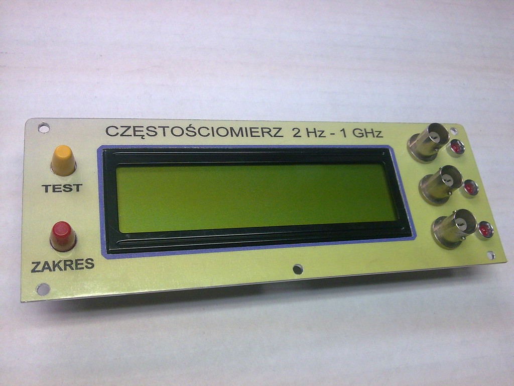
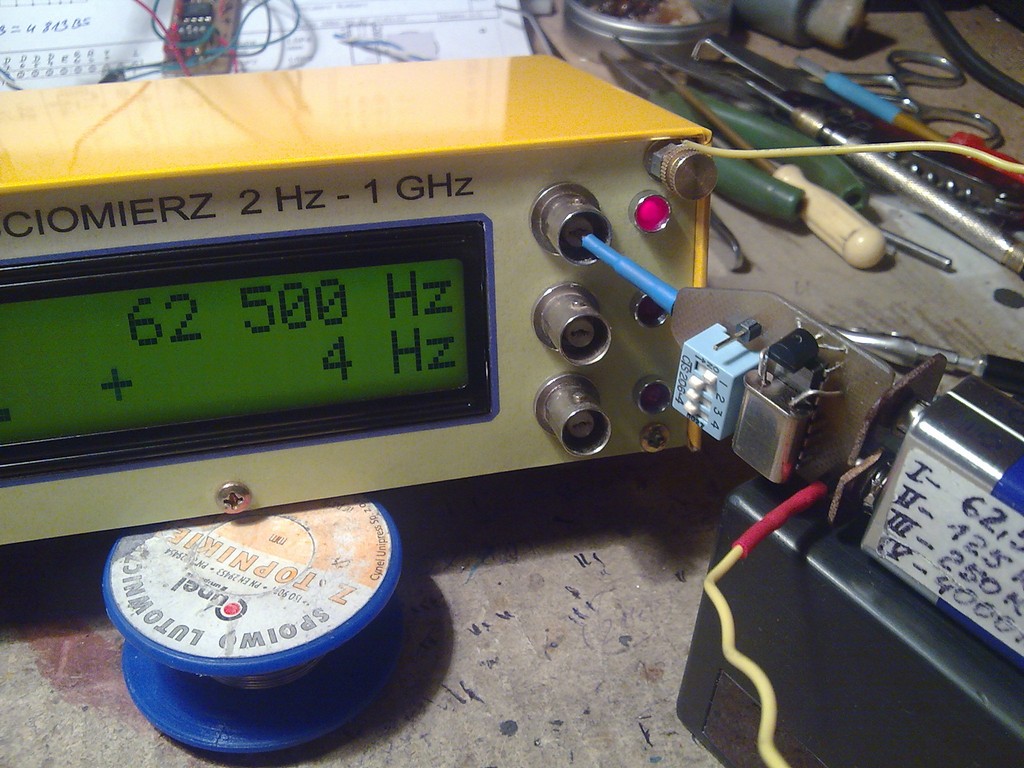
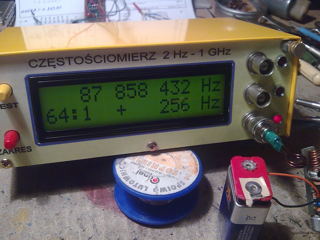
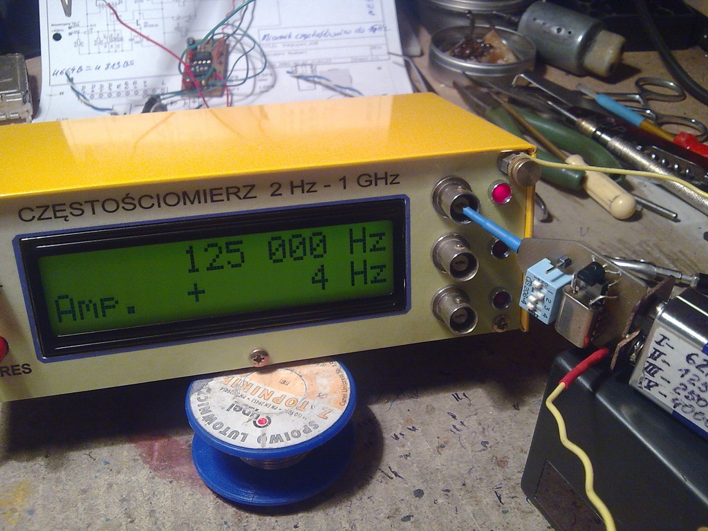
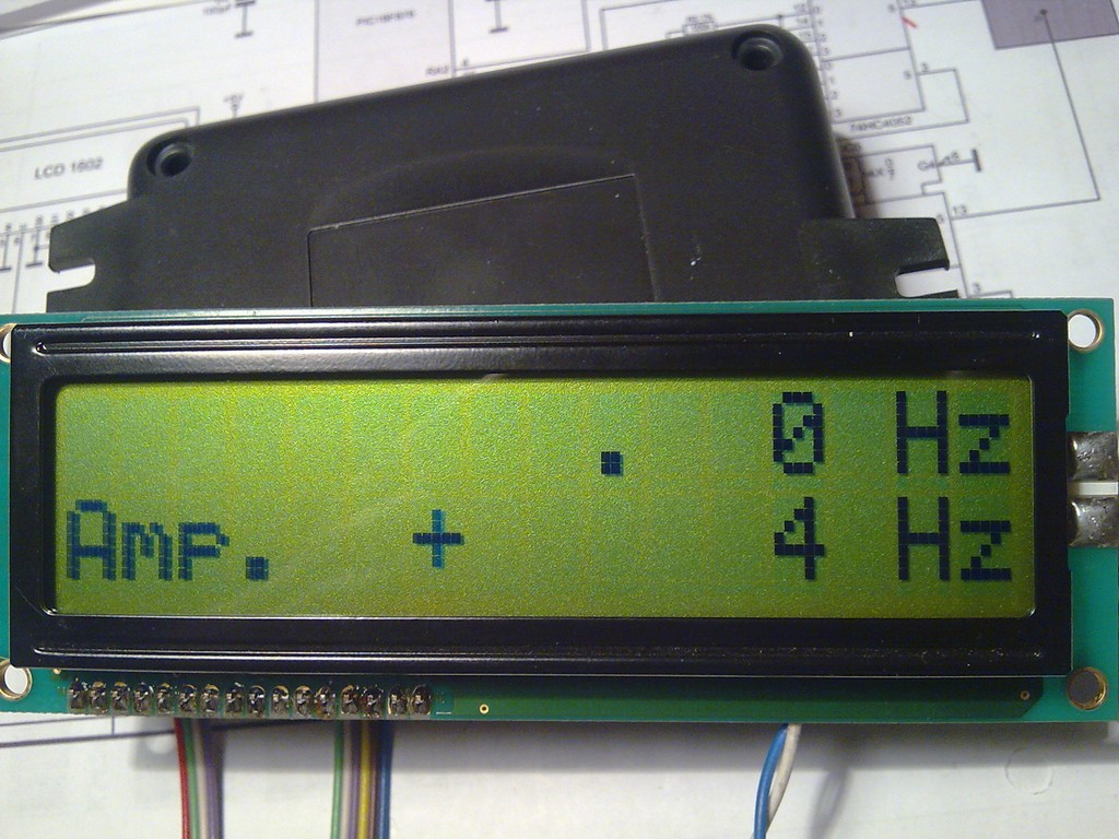
This counter measures in three ranges:
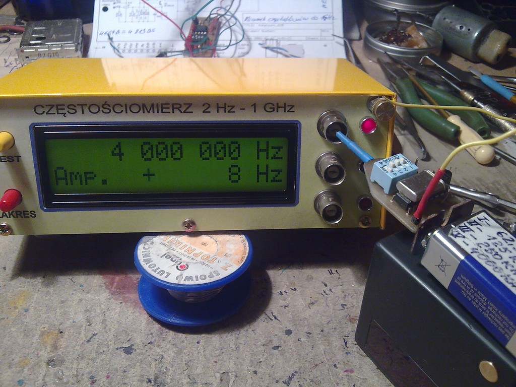
- amplitude
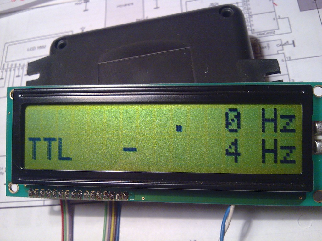
- TTL signals
- frequency up to 1GHz
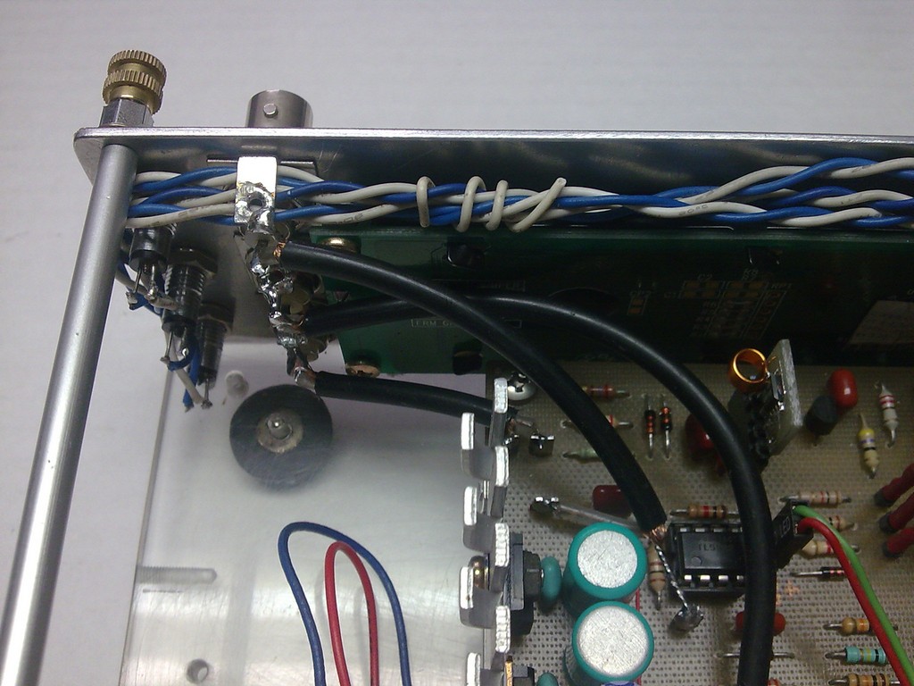
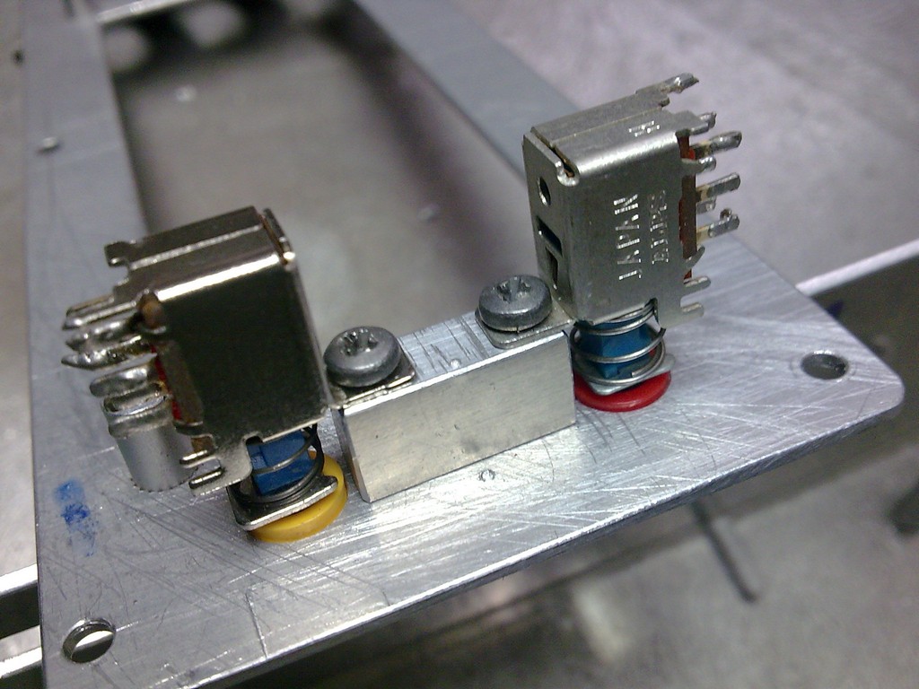
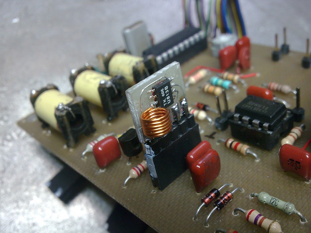
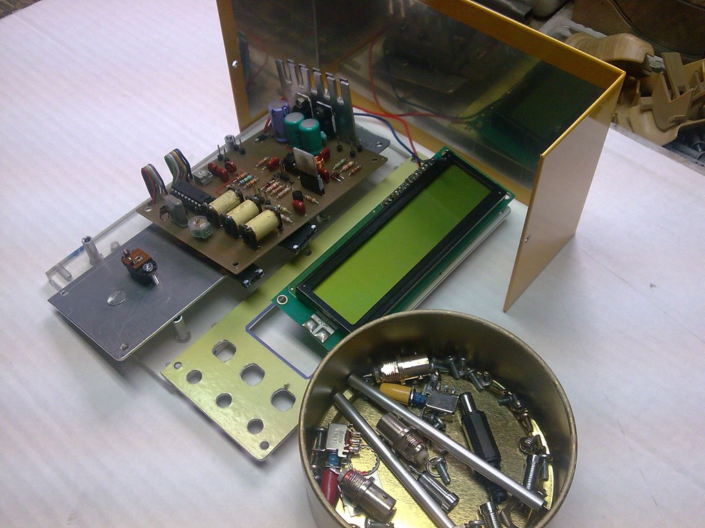
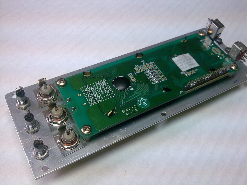
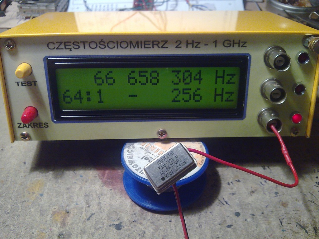
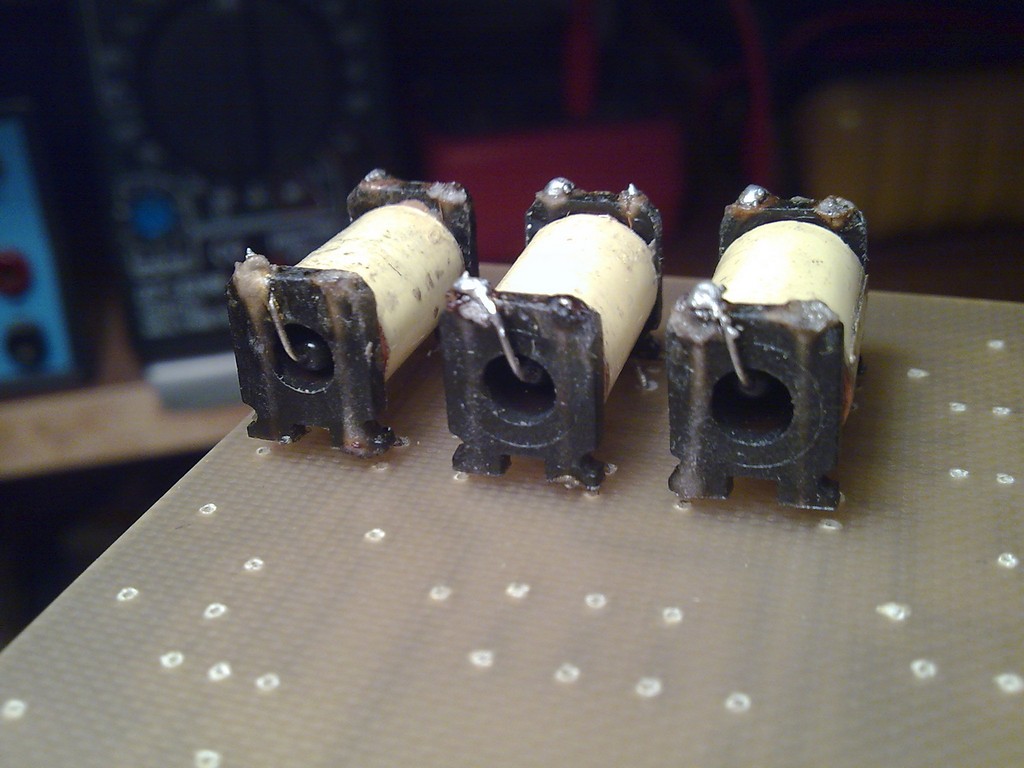
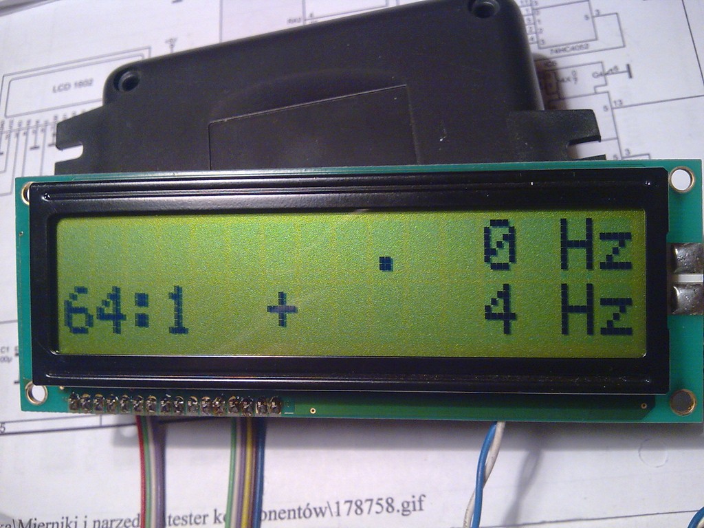
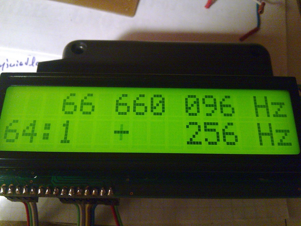
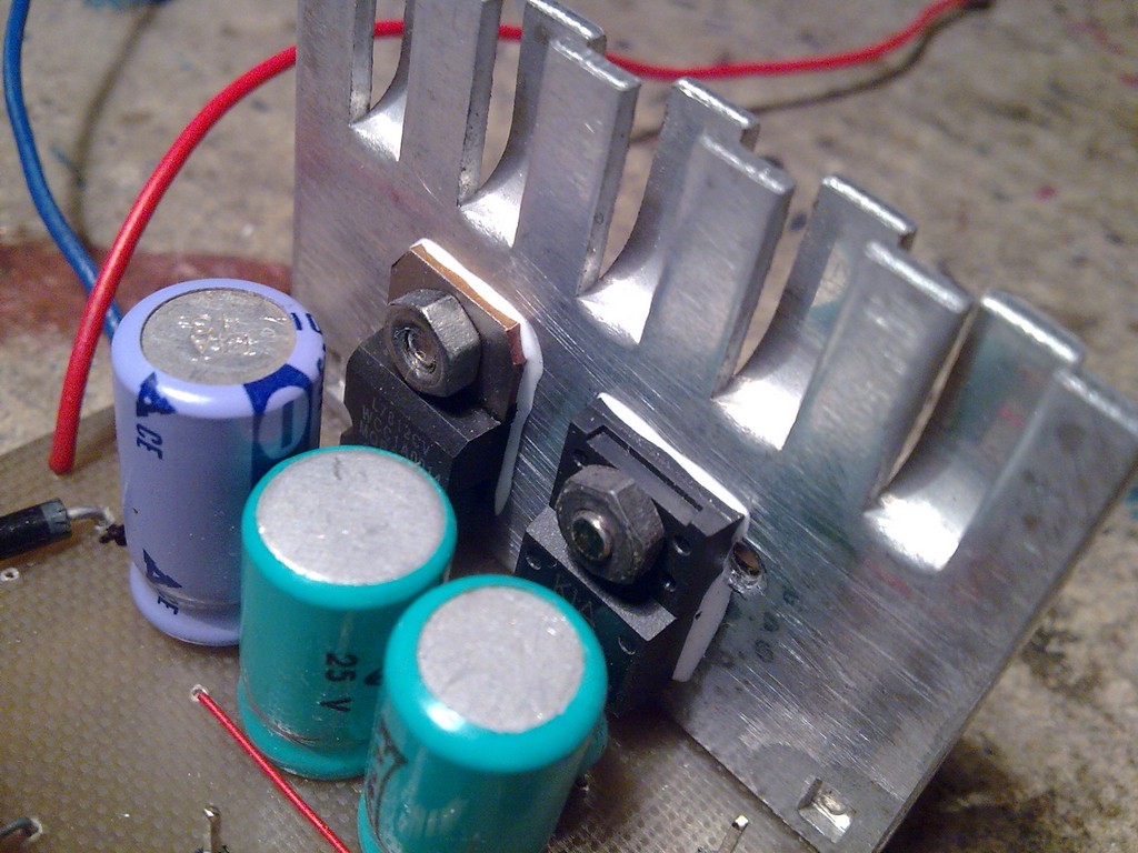
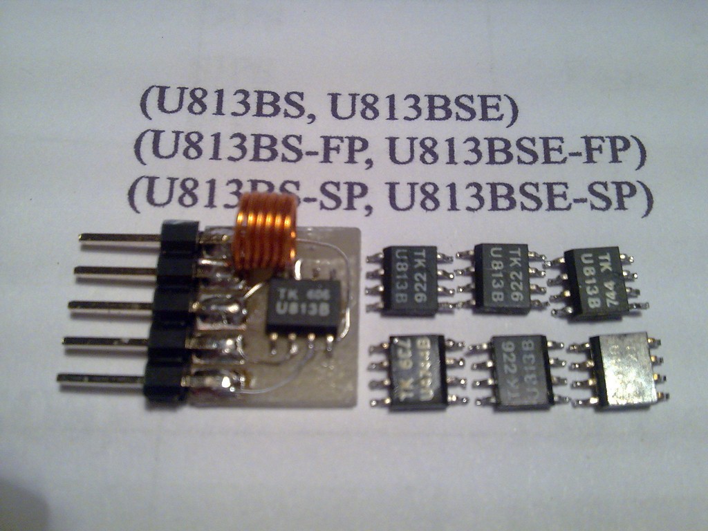
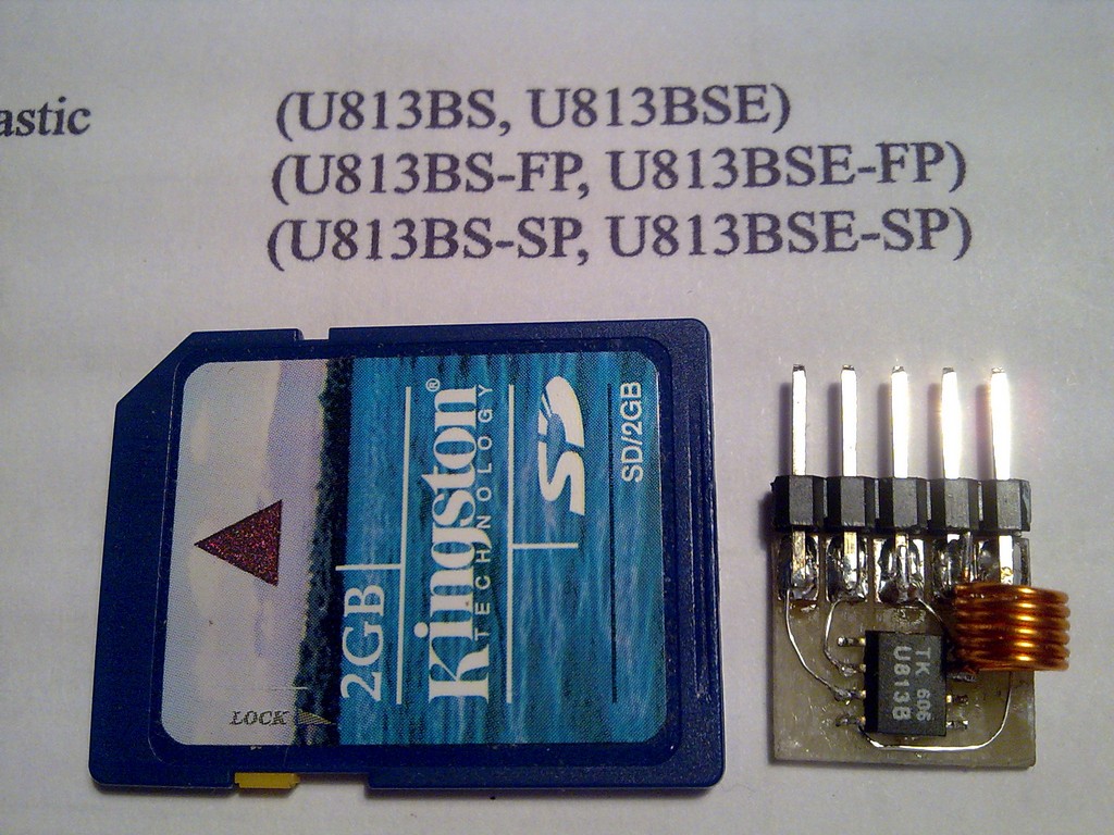
The first and second ranges are up to 50MHz and the third from approximately 40MHz to 1GHz. Temporary switch 'test' is used for the measurement and displaying (on 2x20 display) the own frequency of the counter. Test operates on TTL range. Switch 'zakres' ('range') changes the ranges. The range is displayed on LCD and a LED indicates active measurement socket. Prescaler was desoldered from a TV tuner. Reed relays, ranges switching desoldered elements. It was tailored to the PCB by edging terminals. Coil resistance is about 900 ohm (originally 500 ohm).
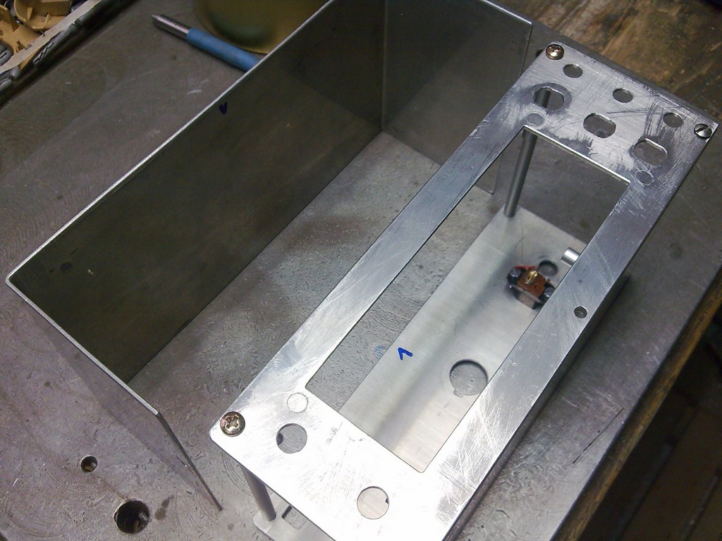
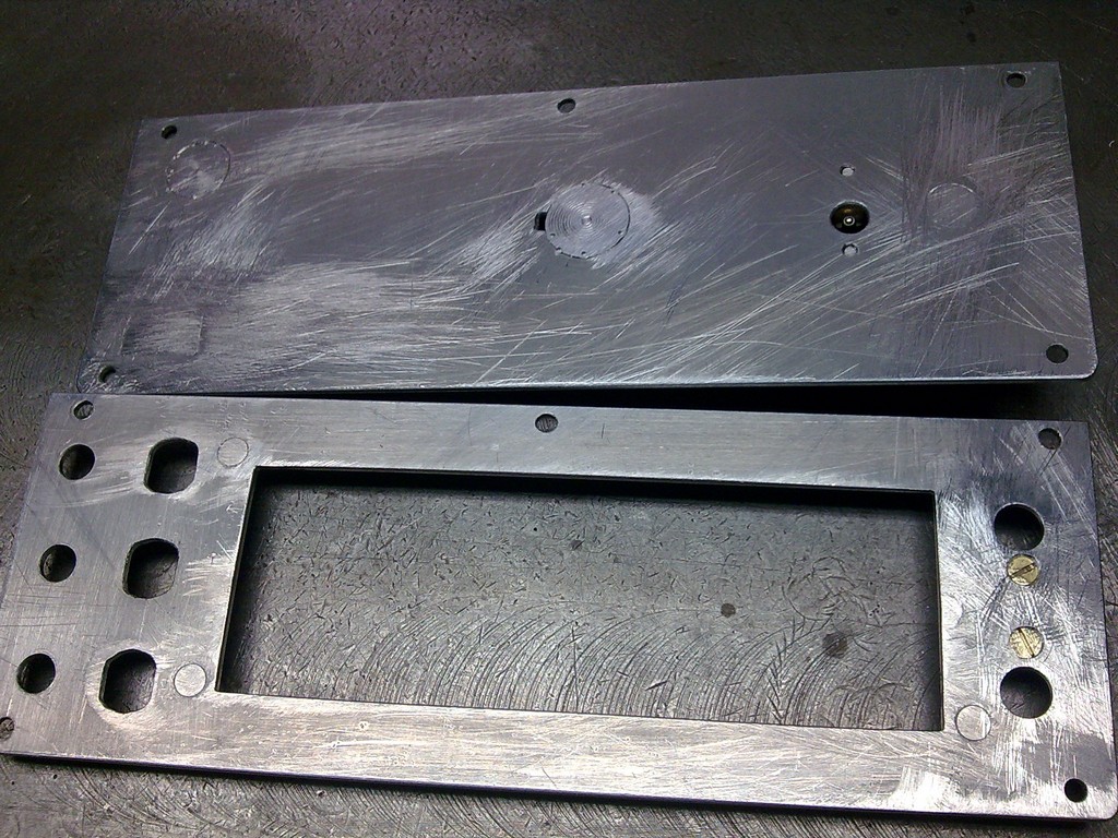
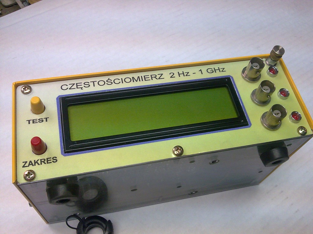
Housing was covered with self-adhesive foil. Front panel was made of aluminum, necessary holes drilled and sanded and then a self-adhesive paper sheer finished the look. And additionally clear self-adhesive foil.
Supply voltage is about 15V. 230MA current consumption.
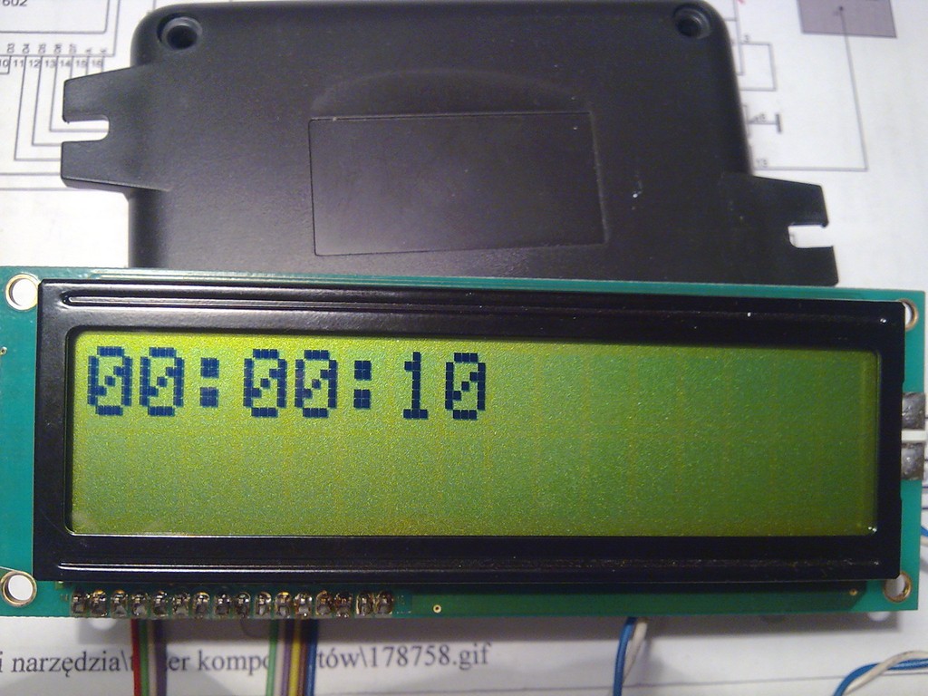
You can calibrate the counter by measuring the time. While pressing the 'range' button, give the supply voltage. The counter runs as a clock counting the time from 1 second to 24 hours. The time can be adjusted with the trimmer. In this way, after a few days accurate indication is made.


Link to original thread (useful attachment) – Częstościomierz 2Hz do 1GHz.