Continue to Site

Welcome to EDAboard.com

Welcome to our site! EDAboard.com is an international Electronics Discussion Forum focused on EDA software, circuits, schematics, books, theory, papers, asic, pld, 8051, DSP, Network, RF, Analog Design, PCB, Service Manuals... and a whole lot more! To participate you need to register. Registration is free. Click here to register now.

FM demodulator in a ratio detector

Status
Not open for further replies.
http://www.tscm.com/NEETS-v12-Modulation.pdf page 3-15 will give you more information.
Thank you for the study materials.


Modulation at 10MHz when the carrier is 90MHz isn't really practical for this kind of demodulator, it works best with narrow deviation. Consider that a 10MHz modulating signal will have sidebands extending close to the carrier frequency itself. You will find it used frequently for recovering audio frequencies (< 15KHz) where the center is 10.7MHz in domestic receivers.

Ok, so I want to design ratio detector that would work for such parameters: carrier frequency 98MHz, modulating signal 100kHz and Index Modulation 25 (I have read that most often the modulation index takes values from 10 to 100, of course it can be 1, but is not recommended). My question: how to choose parameters of ratio detector FM demodulator?

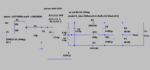
The LTspice schema in post # 19 was modeled on this schema:
1610649563530.png

Oh i forgot to add capacitor c3. My fault!
 

Sorry for spam, but I think I am close solving problem. This is corrected scheme:

1610991694694.png


1610991676219.png


All I have left is to change the ideal diodes to real elements. And further improve the circuit. But now I'm sure the circuit demodulates the fm signal :)
 

I still can't work out what the graphs represent. V(vin) needs to change frequency around the resonant point and V(vout) should rise then fall as the resonant point is passed, your signals seem to be at the same frequency and it is far too low. The resonance assuming L2 and L3 are on the same former will be at 14.711 MHz but your signal is at about 15KHz, out by a factor of 1,000 !

Brian.
 

I changed input voltage (V1) parameter and it's like this:
1611508608938.png


And this is what I receive in AC analysis:
1611508627119.png


Vout is the voltage of output between R1 and R2. Is it correct?
 

Attachments

  • 1611506851906.png
    1611506851906.png
    43.6 KB · Views: 98
  • 1611507003159.png
    1611507003159.png
    13.2 KB · Views: 86
Last edited:

I have no idea what is producing the curves you show but it certainly isn't what a ratio detector should give.
A ratio detector works at one specific frequency, it is decided by the capacitors C1 and C2 and L1, L2 and L3 using the formula f=1/(2 *pi *Sqrt(L*C)) and that makes the C1/L1 combination resonate at about 10.9MHz and C2/L2+L3 combination resonate at about 14.7MHz, it therefore doesn't make any sense to show the plot at much lower frequencies. The circuits should resonate at the same frequency, be coupled together and the frequency sweep should be from about 1MHz below resonance to 1MHz above it.

Brian.
 

Status
Not open for further replies.

Part and Inventory Search

Welcome to EDABoard.com

Sponsor

Back
Top