Continue to Site

Welcome to EDAboard.com

Welcome to our site! EDAboard.com is an international Electronics Discussion Forum focused on EDA software, circuits, schematics, books, theory, papers, asic, pld, 8051, DSP, Network, RF, Analog Design, PCB, Service Manuals... and a whole lot more! To participate you need to register. Registration is free. Click here to register now.

Flyback Design_Problems

Status
Not open for further replies.
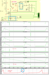
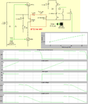
The simulation below with a magnetic saturation model, show how saturation can occur with too small air gapped core. Bottom trace RH picture show gap reduced from 1 mm to 0.5 mm.

- - - Updated - - -

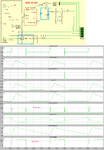
Another set of results with a larger ETD 44 core and 0.5 mm gap.

- - - Updated - - -

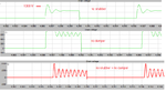
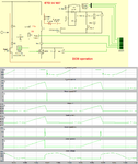
The result of omitting the snubber, damper or both.
 

Attachments

  • ETD29_87.png
    ETD29_87.png
    83.7 KB · Views: 73
  • ETD44_87.png
    ETD44_87.png
    71.5 KB · Views: 73
  • drain_V.png
    drain_V.png
    37 KB · Views: 70
The same ETD 44 core using a non-dissipative clamp instead of RCD. It requires one extra winding on the core.
 

Attachments

  • non_diss_clamp.png
    non_diss_clamp.png
    70.4 KB · Views: 64

I think before you go any further you must decide which mode of operation you are going to design for. Look at the attachment and once you have made that decision according to the "pros" and "cons" we can look at helping you optimizing such a design.

For the amount of power you are talking about, standard RCD snubber losses will be substantial, so it may be worth considering a non dissipating clamp design. It will add to complexity, so that is something to keep in mind also.

I am designing it with the DCM
Can you share a Formula of calculation in both the Modes.
I am using Calonel Maclyman Handbook Example to do The calculations.
Also,i shared the Zip File in the Post
Kindly Help.
 

For just DCM at 180 Vin min, 12V 10A out, the answer falls out as above, 200uH Lpri, 3.6Apk, 4uS Ton for 100kHz, using your 51:5 turns ratio V flyback = 130V (+ spike), 1.8mmm gap in each leg (3) 0.07T peak.
 

You can try this design with an ETD 34/ N87 with 1mm gap together with the alternative clamp. It should work for you.
 

Attachments

  • ETD34_FB.png
    ETD34_FB.png
    65.5 KB · Views: 71

@ E-design, you have simulated a forward converter, NOT a flyback...! so not too relevant to the discussion...
 

I threw it in as an alternative for him to look at, since the snubber losses is so high using the flyback option at his power level.
 

will the zener work instead of resistor ?
 

Its usually a tvs not zener used in a flyback primary clamp if at all….and pure tvs clamps don’t tend to get used unless it’s a really low power flyback (few watts).
So no, you cannot use a tvs, not on its own anyway….you could use one as part of an RCDZ clamp though, because then the resistor takes most of the power, but really, what is your transformer LP,LS and leakage and f(sw), because you need to find out if you even want to do a flyback at this power level, as the clamp components will be dissipating a fair bit if you cant be sure of L(leak) always being low

If you want to see a design of a flyback to your spec, then go to power integrations website, and type in your spec into their free design software, which is called ….i forget….uuuhh…its gone, but you can find out…AAAhh, that’s it “PI Expert” software.

The point of an rcdz clamp is less clamp dissipation in light load.
Oh and flyback RCD clamps usually have a parallel tvs which comes into play during transients such as startup, so as to prevent too high voltage on the fet drain in those transients
 

If going with a pure flyback at these power levels the snubber losses will be problematic if the leakage inductance's are not kept to a minimum. That is not always easy. Simulations showed the wattage of the snubber resistor required can go as high as 40 W (80 W rated for safety) when keeping the drain voltage at a safe peak under 800 V. This assumed a leakage inductance of 25 uH.

- - - Updated - - -

You should look at going to a two-switch flyback. It will require a bit more complexity driving the switches but make life much easier at the end.
 

You should look at going to a two-switch flyback. ...

Excuse my ignorance, but I thought that a two switch forward would have been better. Driving two switches (forward or flyback) should be equally complex, I assume? Please explain.
 

Excuse my ignorance, but I thought that a two switch forward would have been better. Driving two switches (forward or flyback) should be equally complex, I assume? Please explain.

Since you're dealing with a high side driver, it is a bit more complex unless you use a gate driver transformer. The gate transformer will be my choice.

Furthermore, with 2-switch FB, you can only allow 50% max duty cycle.
 

Since you're dealing with a high side driver, it is a bit more complex unless you use a gate driver transformer. The gate transformer will be my choice.
..I suppose you are harking on the same lines as Dr Ridley in his article "gate drive design tips"?

...Anyway, as the link in post #52 explains, both 2 sw forward and 2 sw flyback can easily be dealt with with a high side bootstrap drive ic for the high side fet. (as long as you get a nice layout)

2 sw flyback can have any duty cycle as long as you watch the referred voltages.
 

I think this design comes close to his requirements. It stays under 50% duty cycle, operate in DCM and do away with the snubber problems. So the 1000V rated switches is not needed. It requires a much bigger core with a 1 mm gap though.

- - - Updated - - -

Going with a ETD 49 with primary 30 T and sec 3 T, same 1 mm gap will also work with slightly higher core loss. Going to an even smaller core makes the required air gap too large (>1.5 mm for ETD 44). The standard of-the-shelf EPCOS gapped core is 1 mm maximum.
 

Attachments

  • EDT54.png
    EDT54.png
    53.3 KB · Views: 69
Last edited:

VIN=180-240VDC
VOUT=12V
IOUT=10A
FSW=100KHZ
LP=1.37mH
LS=25uH
k(transformer)=0.99


…the above spec shows that D(max) should be no more than 0.2…otherwise rms secondary current will be too high ......... waveforms in above post show D>0.4, that's too high
 
How is the sim in post #55 in any way accurate? it shows a fwd converter and yet the output current is not in step with the fet current, when the fet is on there should be power flow to the o/p, not zero current...? It needs revisiting...

- - - Updated - - -

@ treez, re post #56, for 1.37mH and 180Vin, the peak current required in Lpri needs to be 1.38A to get enough power thru (130W) at 100kHz, the time required (180V) to ramp to 1.38A is 10.5uS..! longer than a 100kHz period..! so cannot operate at 100kHz...! (or at this high Lpri, or at such a low current) Hence 200uH & 3.6Apk at 100kHz for required power out...! for DCM.

We have built flybacks to 200W off 230Vac mains, it can be done, just need a good transformer and clever snubbing..!
 
How is the sim in post #55 in any way accurate? it shows a fwd converter and yet the output current is not in step with the fet current, when the fet is on there should be power flow to the o/p, not zero current...? It needs revisiting..

Ignore the polarity markings on the windings. It is an early demo version of the software, and sometimes it reverses the polarity of the model opposite to what is shown on the symbol. You can place two identical windings, and the one may operate reverse polarity of the other. It is an annoying bug.
 

[QUOTE
for 1.37mH and 180Vin, the peak current required in Lpri needs to be 1.38A to get enough power thru (130W) at 100kHz, the time required (180V) to ramp to 1.38A is 10.5uS..! longer than a 100kHz period..! so cannot operate at 100kHz...! (or at this high Lpri, or at such a low current) Hence 200uH & 3.6Apk at 100kHz for required power out...! for DCM.

We have built flybacks to 200W off 230Vac mains, it can be done, just need a good transformer and clever snubbing..![/QUOTE]

I made the same calculations which is 122uH.
But with the ETD44/N87 Material, giving calculated values very High gap in the core.
That is 0.78cm,
By Putting 0.78cm Gap, i am able to get the 150-200 uH
Will such gap exist..??
or my calculations are wrong..??
Attached is the Transformer calculations.

Thanks
Marx.
 

Attachments

  • flyback calc.zip
    16 KB · Views: 54

Are you trying to keep your original transformer with 50 T and 5 T and getting the correct inductance value by adjusting the air gap? That will give you that large gap of over 7 mm.

I know EPCOS only has pre-gapped cores up to 1 mm maximum. You will have to modify the turns to use one of these.

If you want to use the ETD 44/ 1mm gap part, then you will have to go with 19 T and 2 T with a higher peak current of about 6A (using 2 switch design).

- - - Updated - - -

If you still want to go with a single switch, then use 25 T and 2 T, but you will have the snubber losses to deal with again. I will suggest you use 2 switches instead.
 
Last edited:

Status
Not open for further replies.

Similar threads

Part and Inventory Search

Welcome to EDABoard.com

Sponsor

Back
Top