Continue to Site

Welcome to EDAboard.com

Welcome to our site! EDAboard.com is an international Electronics Discussion Forum focused on EDA software, circuits, schematics, books, theory, papers, asic, pld, 8051, DSP, Network, RF, Analog Design, PCB, Service Manuals... and a whole lot more! To participate you need to register. Registration is free. Click here to register now.

Flyback Design_Problems

Status
Not open for further replies.

Bjtpower

Full Member level 5
Joined
Dec 24, 2015
Messages
297
Helped
2
Reputation
4
Reaction score
2
Trophy points
1,298
Activity points
3,893
Dear Sir

I have developing the Flyback converter in flyback_ringing.JPG open loop.
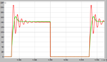
attached image is the Result observed at 70v (Dc) Input.
The waveform is of the Voltage across drain to source i have used the Diode-Zener Snubber but still there are some ringing as you can observe in the Image attached.

Kindly help how to reduce the same as well the causes of ringing In vds so i can Remove the same & Go for the Output.
 

Parameter are
Operating frequency:100KHZ
Core used:ETD49/N27
Lp:1.37mH
Ls:25uH

Circuit is Open loop with input voltage 70v dc..
Turns Ratio:10:1

Kindly Help
Marx
 

your turns ratio is 38.4:1

the ringing is just normal, in places its scope lead noise, in others , just the ringing of L(Leak) with C(drain).
Are you sure N27 is ok for 100khz?...I thought n27 was for lower frequency
 
Last edited by a moderator:
Ringing is the issue of transformer only (other words not an issue its happening all transformer due to low coupling or leakage inductance)
To reduce these ringing you should do interleaved winding (Fro example half primary flowed by secondary then reaming half primary )
 

Ringing is due to poor primary to secondary coupling only


Are you sure N27 is ok for 100khz?...I thought n27 was for lower frequency

No issue, N27 is used for 25Khz to 150Khz application
 
The ringing is not good for health. Use a diode capacitor and see that the ringing is not more than 20% (overshoot) - also ensure that you turn-on hard - is the gate drive sufficient?
 

The ringing doesn't matter too much, if it bothers you you can damp it but it just wasted energy....as described before, you can always interleave wind to reduce leakage.

- - - Updated - - -

N27 may be good to 150khz, but its worth remembering that the flyback trapezoidal waveform at 100khz has harmonics well above 150khz, so its probably better, if you have the choice, to use a higher frequency capable ferrite, -if of course N27 is much much cheaper, then N87 say, then maybe N27 is your choice
 
If this is more than just a college experiment or hobby project, I will put a simple RC damper over the primary. This will cut down on emissions and give a better safety margin for the switching device. Shown is the result of a 330 Ohm and 820p damper.
 

Attachments

  • snubbed.png
    snubbed.png
    34.4 KB · Views: 91
  • FFT.png
    FFT.png
    70.9 KB · Views: 84
Last edited:
does OP actually have an RCD clamp across the primary?

At low power these are often just RC's, as E-design says

You can also have RCDZ clamps if you want to be efficient in light load...RCDZ clamp seems to be an invention of power integrations
 

The size of any snubber depends on the max power you intend to run, it is a good idea to have a snubber on the sec side too - as this helps and reduces the size of the pri side (HV) snubber required.

A Tx with lower leakage (better coupling) from pri to sec will help (make sure insulation requirements are met) and after that it is time to turn to snubbing...!
 

Ringing is the issue of transformer only (other words not an issue its happening all transformer due to low coupling or leakage inductance)
To reduce these ringing you should do interleaved winding (Fro example half primary flowed by secondary then reaming half primary )

Hi Smijesh:
The Transformer is well made by Professional Expert Having Primary Inductance 1.4mH & Leakage Inductance 14 uH (If Shorted Secondary) & It is Interleaved Winding 25 T (P1-P2),5T(sEC),25T(P2-P3)
DSC_0012.JPG
Now changes i made in the Attached Trafo is that i used the ETD49 (N27) Material.
The ringing are very worse as you can see the Image attached.

I tried the RCDZ Snubbers (R=680 OHM,C=680 pF,Vz=360v), in this operations i got the very well Snubbing operation (Image attached) but after few minutes,Gate Resistor 4.7 ohm Burnt Out.
After Snubber operations
after snubber.jpg

- - - Updated - - -

The ringing is not good for health. Use a diode capacitor and see that the ringing is not more than 20% (overshoot) - also ensure that you turn-on hard - is the gate drive sufficient?

Hello c_Mitra,
I am using gate driver of 4 Ampere of silabs.

What is Turn on Hard n how to achieved..?

- - - Updated - - -

your turns ratio is 38.4:1

Your turns ratio is 38.4:1 ..??
My secondary turns are:5
My Pri Turns are :51

i am not using the wire probes of scopes , i am using it with the short leads of wire

- - - Updated - - -

Why my Gate resistor Burnt.??
 

Can you give more information about the type of MOSFET, diodes and output power? Maybe you can post your schematic as well.
 

I assume the gate resistor burn't out as the fet had died? from in-sufficient heatsinking?

Your turn off (& turn on) is too aggressive, try a 22 ohm gate resistor (0.5 watt) to limit the turn off and turn on speeds this will lessen the turn off spike and help your output diode too, from the scope shots you are well into continuous operation with a high duty cycle - unfortunately this will always give problems with spikes on the o/p diodes and lots of RFI...! and heat in the fet...

- - - Updated - - -

A big snubber across your o/p diode will help a lot too...!
 

Can you give more information about the type of MOSFET, diodes and output power? Maybe you can post your schematic as well.

Hi E-Design
Please find the Details
Mosfet used:**broken link removed**
C2M0080120D MOSFET.JPG
Diode Details:https://www.fairchildsemi.com/datasheets/FF/FFPF30UA60S.pdf
Driver Details:https://www.silabs.com/Support Documents/TechnicalDocs/Si823x.pdf

Schematics as actual like Flyback Transformers.

- - - Updated - - -

I assume the gate resistor burn't out as the fet had died? from in-sufficient heatsinking?

A big snubber across your o/p diode will help a lot too...!

I used the Big Heatsink on both the side (Input Mosfet as well Output diode)

also Mosfet Temperature is under Limit only output Diode Heatsink gets heated upto 60degrees at 10amp of output current.
I posted Mosfet as well Diode details ABOVE.

Also they have recommended to use a 4.7ohm/0.25 watt Resistor which i used the same.
N i also Lost that Mosfet TOO..
 

how much power are you trying to process? more than 200W? if so you will need large snubbers.
 

how much power are you trying to process? more than 200W? if so you will need large snubbers.

Now we are using at 12volt 10 amp at output side.

- - - Updated - - -

from the scope shots you are well into continuous operation with a high duty cycle - unfortunately this will always give problems with spikes on the o/p diodes and lots of RFI...! and heat in the fet...

- - - Updated - - -

A big snubber across your o/p diode will help a lot too...!

Here duty cycle is 42%
 

I am sticking on previous post about the ringing . But I surprise when I see your transformer design. You are using unmatched transformer for your application.

See the formula ,
L pri = Vin*Dmax/Ipk*F
70*0.5/10.37*100000= 33.7uH
Ipk =Iin *5.5
Air gap required for fly back topologies to store energy when the switch closed, Use below equation to find air gap
Air gap in meter =.4*3.14*Lpri*Ipk*Ipk/Area of cross section of core*0.4*0.4

For 120W power ETD 39 will do better
 

At 12V (13.8) and 10A out, try a 4.7 ohm 3W resistor and 200V 10nF cap (low loss film type) across your o/p diode with short leads, this will really help the spike & ringing for the fully continuous design you are trying to get going... try to keep the snubber non inductive - i.e. resistors in parallel to get the 4.7 ohm, not a big ugly wirewound type...
you may have to vary the part values a little to get to the optimum...
 

I am sticking on previous post about the ringing . But I surprise when I see your transformer design. You are using unmatched transformer for your application.

See the formula ,
L pri = Vin*Dmax/Ipk*F
70*0.5/10.37*100000= 33.7uH
Ipk =Iin *5.5
Air gap required for fly back topologies to store energy when the switch closed, Use below equation to find air gap
Air gap in meter =.4*3.14*Lpri*Ipk*Ipk/Area of cross section of core*0.4*0.4

For 120W power ETD 39 will do better

Hi Smijesh
I have designing the Flyback for the 180 dc -240 v dc.

i have calculated the transformer values and it is coming 130uH But i am using a transformer with the 1.6mH so that input current will draw less.

Coming back to the Problem when gate to source get shorted.
i checked at the 140 v input, the gate waveform at turn on going beyond 20v (I think that is damaging the Mosfet (Gate to Source short). i am not sure) attached image with the Post.
mosfet gate waveform at 140v dc.JPG
 

You need, 1k gate to source..! AND 22 ohm resistor to the gate, this will limit the VHF oscillations on the gate,,,!

A smaller value for Lpri (bigger core gap) will get you closer to DCM, discontinuous operation, which is better for the o/p diode and for generating RFI....!

- - - Updated - - -

plugging in the values for just DCM operation (@180VDC in min, 130W) gives L opt = 200uH, Ipk = 3.6A, 100kHz, Ton = 4uS (max).

Using these will give you best operation. For Iout = 10A average, Ipk = 40A, so large high quality electrolytics needed to soak up the current peak & ripple... say 5 x 470uF at a minimum.
 
Status
Not open for further replies.

Similar threads

Part and Inventory Search

Welcome to EDABoard.com

Sponsor

Back
Top